
Related Manuals for Gemu 1236


Summary of Contents for Gemu 1236
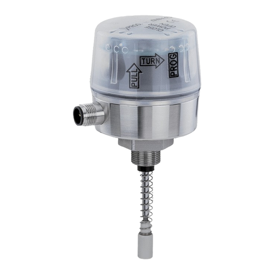
- Page 1 GEMÜ 1236 24V, 3S, 4S Electrical position indicator Operating instructions further information webcode: GW-1236...
- Page 2 All rights including copyrights or industrial property rights are expressly reserved. Keep the document for future reference. © GEMÜ Gebr. Müller Apparatebau GmbH & Co. KG 11.06.2019 GEMÜ 1236 2 / 24 www.gemu-group.com 24V, 3S, 4S...
-
Page 3: Table Of Contents
12 Error clearance ............18 13 Inspection and maintenance ........20 14 Disassembly ............. 20 15 Disposal ..............20 16 Returns ..............20 17 Declaration of conformity according to 2014/30/EU (EMC Directive) ............21 3 / 24 www.gemu-group.com GEMÜ 1236 24V, 3S, 4S... -
Page 4: General Information
The following signal words and danger levels are used: DANGER Imminent danger! ▶ Non-observance can cause death or severe injury. WARNING Potentially dangerous situation! ▶ Non-observance can cause death or severe injury. GEMÜ 1236 4 / 24 www.gemu-group.com 24V, 3S, 4S... - Page 5 ▶ Non-observance can cause moderate to light injury. NOTICE Potentially dangerous situation! ▶ Non-observance can cause damage to property. The following symbols for the specific dangers can be used within a warning note: Symbol Meaning Danger of explosion www.gemu-group.com 5 / 24 GEMÜ 1236 24V, 3S, 4S...
-
Page 6: Safety Information
14. Do not carry out any maintenance work and repairs not described in this document without consulting the manufacturer first. In cases of uncertainty: 15. Consult the nearest GEMÜ sales office. GEMÜ 1236 6 / 24 www.gemu-group.com 24V, 3S, 4S... -
Page 7: Product Description
3 Product description 3 Product description 3.1 Construction Item Name Materials Housing cover Housing base Stainless steel Electrical connection PVDF Adapter piece PVDF Mounting kit, valve specific Stainless steel Seals EPDM, PUR www.gemu-group.com 7 / 24 GEMÜ 1236 24V, 3S, 4S... - Page 8 3.2.2 LED conditions Function CLOSED ERROR OPEN High visibility LED Valve in OPEN position Valve in CLOSED position Programming mode OPEN / CLOSED flash alternately flashes alternately LED conditions lit (on) irrelevant flashes GEMÜ 1236 8 / 24 www.gemu-group.com 24V, 3S, 4S...
-
Page 9: Correct Use
3.4 Function The GEMÜ 1236 electrical position indicator shows the position of the valve. When the valve is opened, the spindle in the elec- trical position indicator moves upwards and indicates that the valve is OPEN using the high visibility LEDs and communication interface. -
Page 10: Order Data
M125 M12 plug, 5-pin 6 Travel sensor version Potentiometer, 30 mm length 7 Housing material Base 1.4301, PP cover, M16 thread, 1.4305 10 / 24 10 / 24 GEMÜ 1236 GEMÜ 1236 www.gemu-group.com www.gemu-group.com 24V, 3S, 4S 24V, 3S, 4S... -
Page 11: Technical Data
Reverse battery protection: Line fuse 630 mA medium time lag (not applicable for operation with IO-Link Master) Current consumption: typically 30 mA Electrical connection 1 x 5-pin M12 plug (A-coded) type: www.gemu-group.com 11 / 24 GEMÜ 1236 24V, 3S, 4S... -
Page 12: Dimensions
7 Dimensions ø 60 TURN SW 27 Travel sensor version Code 65.5 87.5 112.5 30.5 55.5 19.0 41.0 66.0 Dimensions in mm GEMÜ 1236 12 / 24 www.gemu-group.com 24V, 3S, 4S... -
Page 13: Manufacturer's Information
2. Remove optical position indicator 2 and / or protective cap 1 from the actuator top. 9.2 Preparations for installation of the valve (quarter turn actuator) 1. Move the actuator A into zero position (actuator vented). 2. Remove the screw 1 from the trigger cam 2. www.gemu-group.com 13 / 24 GEMÜ 1236 24V, 3S, 4S... - Page 14 3. Screw adapter 3 into the actuator opening as far as it will go and tighten. 9.5 Mounting kit assembly (quarter turn actuator) ● Fit the adapter 3 with screws 4 to the actuator A. GEMÜ 1236 14 / 24 www.gemu-group.com...
- Page 15 9.7 Installing the electrical position indicator (linear actuator) CAUTION Incorrect installation of the product. ▶ Damage to the housing. Only tighten the product using the spanner flats provided for this purpose. ● 9 (SW 27) www.gemu-group.com 15 / 24 GEMÜ 1236 24V, 3S, 4S...
-
Page 16: Electrical Connection
10 Electrical connection 10.1 Device version 3S/4S Description U, 24 V DC, supply voltage U, GND 24 V DC, Open end position output n. c. 24 V DC, Closed end position output GEMÜ 1236 16 / 24 www.gemu-group.com 24V, 3S, 4S... -
Page 17: Programming The End Positions
4. Open valve until end position is reached. 5. Close valve until end position is reached. 6. Turn the housing cover back clockwise and press it down. ð The end positions are set. www.gemu-group.com 17 / 24 GEMÜ 1236 24V, 3S, 4S... -
Page 18: Error Clearance
OPEN and CLOSED flash alternately Sensor error OPEN position CLOSED position Short-circuit Output OPEN signal output Output CLOSED OPEN+CLOSED Internal error OPEN and CLOSED flash simultaneously Supply voltage too low lit (on) irrelevant flashes GEMÜ 1236 18 / 24 www.gemu-group.com 24V, 3S, 4S... - Page 19 Communication error Communication disturbed or interrupted Check the wiring Supply voltage too low Supply voltage too low Ensure supply voltage in accordance with chapter "Technical data" Internal error Memory error Return device www.gemu-group.com 19 / 24 GEMÜ 1236 24V, 3S, 4S...
-
Page 20: Inspection And Maintenance
1. Clean the product. 2. Request a return delivery note from GEMÜ. 3. Complete the return delivery note. 4. Send the product with a completed return delivery note to GEMÜ. GEMÜ 1236 20 / 24 www.gemu-group.com 24V, 3S, 4S... -
Page 21: Declaration Of Conformity According To 2014/30/Eu (Emc Directive)
GEMÜ Gebr. Müller Apparatebau GmbH & Co. KG Fritz-Müller-Straße 6-8 74653 Ingelfingen-Criesbach, Germany declare that the product listed below complies with the safety requirements of the EMC Directive 2014/30/EU. Description of the product: GEMÜ 1236 Device version: 3E, 3S, 4E, 4S Technical standards used: Interference resistance: EN 61000-6-2 IO-Link Spec 1.1... - Page 22 22 / 24 GEMÜ 1236 24V, 3S, 4S...
- Page 23 23 / 24 GEMÜ 1236 24V, 3S, 4S...
- Page 24 GEMÜ Gebr. Müller Apparatebau GmbH & Co. KG Subject to alteration Fritz-Müller-Straße 6-8, 74653 Ingelfingen-Criesbach, *88601606* Germany 06.2019 | 88601606 Tel. +49 (0)7940 123-0 · info@gemue.de www.gemu-group.com...
Need help?
Do you have a question about the 1236 and is the answer not in the manual?
Questions and answers