Table of Contents
Advertisement
Quick Links
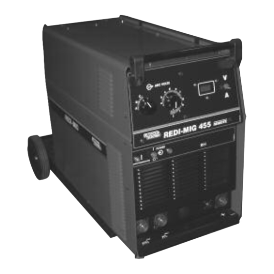
REDI-MIG 455 Remote
Semi Automatic Arc Welding Machine
This manual applies to
Part No.
Code
Description
K32033-1
70112
REDI-MIG 455
Remote
Lincoln Electric welders are designed and built with safety in mind. However, your overall safety can be increased by
proper installation . . . and thoughtful operation on your part. Read and observe the general safety precautions on
page 2 and follow specific installation and operating instructions included in this manual.
IMA 603
OPERATING MANUAL
Volts
380-415
SAFETY DEPENDS ON YOU
Most importantly, think before you act and be careful.
THE LINCOLN ELECTRIC COMPANY
(AUSTRALIA) PTY. LTD.
THE LINCOLN ELECTRIC CO. U.S.A.
Associated Subsidiaries in Australasia, Asia, Europe, North and South America.
THE WORLD'S LEADER IN WELDING AND CUTTING PRODUCTS
A.B.N. 36 000 040 308
SYDNEY. AUSTRALIA
A Subsidiary of
REDI-MIG 455 Remote
IMA 603C
November 2005
EMC Compliant
Page
Advertisement
Table of Contents

Related Manuals for Lincoln Electric 70112


Summary of Contents for Lincoln Electric 70112
- Page 1 SAFETY DEPENDS ON YOU Lincoln Electric welders are designed and built with safety in mind. However, your overall safety can be increased by proper installation . . . and thoughtful operation on your part. Read and observe the general safety precautions on page 2 and follow specific installation and operating instructions included in this manual.
-
Page 2: Arc Welding Safety Precautions
PROTECT YOURSELF AND OTHERS FROM POSSIBLE SERIOUS INJURY OR DEATH. READ AND UNDERSTAND BOTH THE SPECIFIC INFORMATION GIVEN IN THE OPERATING MANUAL FOR THE WELDER AND/OR OTHER EQUIPMENT TO BE USED AS WELL AS THE FOLLOWING GENERAL INFORMATION. ARC WELDING SAFETY PRECAUTIONS ARC RAYS can burn ELECTRIC SHOCK can kill 1. - Page 3 3. Should the primary cord be damaged, a special cord is required, and is available from Lincoln Electric. 4. Parts should be ordered from Lincoln, its offices or the nearest Authorised Field Service Shop. (The “Lincoln Service Directory”...
-
Page 4: Welding, Emf & Pacemakers
WELDING, EMF & PACEMAKERS All welders should follow safe practices that minimise their Welders with pacemakers exposure to electric and magnetic fields (EMF). There is no question that the fields in arc welding can interfere For welders wearing implanted pacemakers, safe welding with a pacemakers function. - Page 5 Welding equipment should be connected to the mains supply reproduced from British Standard EN 50199) according to the manufacturer’s recommendations.If interference • for using with other Lincoln Electric/LiquidArc equipment. occurs, it may be necessary to take additional precautions such • designed for industrial and professional use.
- Page 6 Thank You for selecting a QUALITY product by Lincoln Electric. We want you to take pride in operating this Lincoln Electric Company product - as much pride as we have in bringing this product to you! Please Examine Carton and Equipment for Damage Immediately When this equipment is shipped, title passes to the purchaser upon receipt by the carrier.
- Page 7 INDEX Page Section 1 INSTALLATION Location Connection to Mains Supply Shielding Gas Supply (for the Gas Metal Arc Welding Process) Gun and Cable Installation Output Polarity Connection Section 2 OPERATING INSTRUCTIONS Duty Cycle Control Panel Section 3 SETTING UP FOR WELDING Section 4 WELDING Changing Electrode Size and Type...
-
Page 8: Product Description
PRODUCT DESCRIPTION The REDI-MIG 455 Remote when combined with either KA1443-2KIT or KA1443-2KITM optional accessory kits offers a remote wire feeder and a separate Constant Voltage DC arc welding machine. It combines a solid state power source with electronically controlled wire feeding equipment. -
Page 9: Gun And Cable Installation
Set gas cylinder on rear platform of the machine. Hook 1.4 Gun and Cable Installation WARNING chain in place to secure cylinder to rear of welder. Remove the cylinder cap. Inspect the cylinder valve for damaged threads, dirt and dust. For cylinders having an external thread fitting, remove any dust and dirt from the Turn the welder power switch off before installing gun and threads with a clean cloth. -
Page 10: Section 2 - Operating Instructions
Section 2 - OPERATING INSTRUCTIONS WARNING 2.2 Control Panel Power Switch • Do not touch electrically live The mains power switch is a two position toggle switch and parts or electrode with skin or is marked “POWER”. When the toggle switch is pressed wet clothing. - Page 11 Burnback Control * Use this same toggle switch to operate the wire feed motor and “cold” inch the wire, by pushing the toggle switch This control is located in the REDI-MIG 4D wire feed downwards. compartment. The burnback control adjusts the time period from when the drive motor stops until the power source and 2 Step/4 Step Trigger Operation * gas solenoid are switched off.
-
Page 12: Section 3 - Setting Up For Welding
Section 3 - SETTING UP FOR WELDING The following items are required: Obtain a gap between the wire feed roll and the pressure roll by lifting the cam latch. Feed the wire end into the guide tube, A reel of wire of suitable size and type . between the drive rolls, and into the “Euro”... - Page 13 IMA 603C REDI-MIG 455 Remote Page 13...
- Page 14 Page 14 REDI-MIG 455 Remote IMA 603C...
-
Page 15: Section 4 - Welding
Section 4 - WELDING WARNING All required equipment for aluminium welding is supplied in the optional 1.2mm Aluminium Feeding Kit (KA1440-5 to suit REDI-MIG 360 torch or KA1440-3 to suit Magnum 400 When the gun trigger is pressed (2 mode) or pressed and torch). -
Page 16: Section 5 - Learning To Weld
Section 5 - LEARNING TO WELD No one can learn to weld simply by reading about it. Skill 5.2 The Self-Shielded (Gasless) comes only with practice. The following pages will help the FCAW Welding Arc (DC-) inexperienced operator to understand welding and develop this skill. - Page 17 5.3 The GMAW (MIG) Welding Arc (DC+) Regardless of the type of metal being welded, in order to get a quality weld, it is important that the metal is free of oil, paint, rust or other contaminants. Figure 2 illustrates the GMAW (MIG) welding arc. Solid wire does not contain fluxes or ingredients to form its own 5.6 Machine Set up for the Self-Shielded shielding and no slag forms to protect the molten weld...
- Page 18 2. The Correct Way To Strike An Arc Helpful Hints 1. Be sure the work clamp makes good electrical 1. For general welding, it is not necessary to weave the contact to the work. arc, neither forward or backward nor sideways. Weld along at a steady pace.
-
Page 19: Welding Techniques For The Gmaw (Mig) Process
When you are sure that you can hold the correct electrical When using an open arc process, it Is necessary to use correct eye, head and body protection. stickout, with a smooth “crackling” arc start moving. Look at the molten puddle constantly, and look at the “ridge” where Protect yourself and others, read “ARC RAYS can burn”... -
Page 20: Butt Welds
Figure 10 Figure 10 Butt weld Lap weld Helpful Hints 1. For general welding, it is not necessary to weave the arc, neither forward or backward nor sideways. Weld along at a steady pace. You will find it easier. 2. When welding on thin plate, you will find that you will have to increase the welding speed, whereas when Edge weld Fillet weld... - Page 21 5.13 Fillet Welds The important thing is to continue lowering the entire arm as the weld is made so the angle of the gun does not change. Move the electrode wire fast enough that the slag When welding fillet welds, it is very important to hold the does not catch up with the arc.
- Page 22 If Arc Blow Occurs (in order of importance): Note: Try different ground connection locations before adjusting procedures. 1. Decrease torch angle. 2. Increase stickout. 3. Decrease voltage. To Reduce Spatter (in order of importance): 4. Decrease WFS (wire feed speed. 1.
-
Page 23: Section 6 - Maintenance
3. Keep gun cable clean by following maintenance working on equipment. instructions. ELECTRIC SHOCK 4. Use only clean, rust-free wire. Lincoln Electric wires • Do not touch electrically hot parts. can kill have proper surface lubrication. 5. Replace contact tip when the arc starts to become 6.1 Routine Maintenance... -
Page 24: Section 7 - Accessories
Section 7 - ACCESSORIES ° Drive Rolls for mild steel, stainless steel and aluminium for ° 1.2mm Flux Cored, Gas and Gasless Welding Kit, solid wires as well as for flux cored wires. See your nearest complete with 2 x 0.9, 1.2mm knurled drive rolls, 0.9- Lincoln distributor for details. -
Page 25: Section 9 - Troubleshooting
Section 9 - TROUBLESHOOTING WARNING • Have an electrician install and service this equipment. • Turn the input power off at the fuse box, or unplug input lead before working on equipment. ELECTRIC SHOCK • Do not touch electrically hot parts. can kill Problem Possible Cause... - Page 26 TROUBLESHOOTING What To Do Problem Possible Cause No wire feed, although arc Defective wire feed motor or wire drive Measure the voltage between the motor voltage is present. control PC board. leads (54) and (53) when the Gas Purge/Wire Inch toggle switch is pressed downwards.
- Page 27 CODE NO. 70112 Operating Manual ............. .REDI-MIG 455 Remote...
-
Page 28: General Assembly
General Assembly AP-221C Operative: Nov 2005 Supersedes: Page 28 REDI-MIG 455 Remote IMA 603C... - Page 29 AP-221C1 Operative: Nov 2005 Supersedes: # Indicates a change this printing. * Items not illustrated. Use only the parts marked “X” in the column under the heading number called for in the model index page. Recommended Spare Parts are highlighted in bold Nut, bolt and washer sizes are given so they may be procured locally.
-
Page 30: Front Panel Assembly
Front Panel Assembly AP-221D Operative: Nov 2005 Supersedes: Page 30 REDI-MIG 455 Remote IMA 603C... - Page 31 AP-221D1 Operative: Nov 2005 Supersedes: # Indicates a change this printing. * Items not illustrated. Use only the parts marked “X” in the column under the Recommended Spare Parts are highlighted in bold heading number called for in the model index page. Nut, bolt and washer sizes are given so they may be procured locally.
- Page 32 Casework Assembly AP-221E Operative: Nov 2005 Supersedes: Page 32 REDI-MIG 455 Remote IMA 603C...
- Page 33 AP-221E1 Operative: Feb 2002 Supersedes: Sep 2001 # Indicates a change this printing. * Items not illustrated. Use only the parts marked “X” in the column under the Recommended Spare Parts are highlighted in bold heading number called for in the model index page. Nut, bolt and washer sizes are given so they may be procured locally.
-
Page 34: Wiring Diagram
Wiring Diagram AP-221W Operative: Nov 2005 Supersedes: Page 34 REDI-MIG 455 Remote IMA 603C... - Page 35 AP-56 Operative: Nov 2003 REDI-MIG 4D Remote Supersedes: May 2001 KA1435 Model Index DO NOT attempt to use this Parts List for machine if its code NUMBERS IN THE TABLE BELOW INDICATE WHICH number is not listed. Contact the Service Department for any COLUMN TO USE IN EACH PARTS LIST FOR EACH code numbers not listed.
-
Page 36: Panel Assembly
Panel Assembly AP-56C Operative: Nov 2003 Supersedes: May 2001 AG 1412-1 (A14-4-00) Page 36 REDI-MIG 455 Remote IMA 603C... - Page 37 AP- 56-C1 Operative: Nov 2003 Supersedes: May 2001 # Indicates a change this printing. * Items not illustrated. Use only the parts marked “X” in the column under the heading number called for in the model index page. Recommended Spare Parts are highlighted in bold Nut, bolt and washer sizes are given so they may be procured locally.
- Page 38 NOTES Page 38 REDI-MIG 455 Remote IMA 603C...
- Page 39 Wiring Diagram 4D Remote AP- 56W Operative: May 2001 Supersedes: IMA 603C REDI-MIG 455 Remote Page 39...
-
Page 40: Wire Drive Assembly
Wire Drive Assembly AP-56-D Operative: Supersedes: 5,6,7,8 10,11,12 Ref: 4111 Page 40 REDI-MIG 455 Remote IMA 603C... - Page 41 AP-56-D1 Operative: Apr 2004 Supersedes: # Indicates a change this printing. * Items not illustrated. Use only the parts marked “X” in the column under the heading number called for in the model index page. Recommended Spare Parts are highlighted in bold Nut, bolt and washer sizes are given so they may be procured locally.
- Page 42 Wire Drive Assembly AP-56-E Operative: Apr 2004 Supersedes: Ref: 410 Page 42 REDI-MIG 455 Remote IMA 603C...
- Page 43 AP-56-E1 Operative: Apr 2004 Supersedes: # Indicates a change this printing. * Items not illustrated. Use only the parts marked “X” in the column under the heading number called for in the model index page. Recommended Spare Parts are highlighted in bold Nut, bolt and washer sizes are given so they may be procured locally.
- Page 44 Wire Drive Assembly AP-56-F Operative: Apr 2004 Supersedes: Ref: 410-2 Page 44 REDI-MIG 455 Remote IMA 603C...
- Page 45 AP-56-F1 Operative: Apr 2004 Supersedes: # Indicates a change this printing. * Items not illustrated. Use only the parts marked “X” in the column under the heading number called for in the model index page. Recommended Spare Parts are highlighted in bold Nut, bolt and washer sizes are given so they may be procured locally.
- Page 46 NOTES Page 46 REDI-MIG 455 Remote IMA 603C...
- Page 47 NOTES IMA 603C REDI-MIG 455 Remote Page 47...
- Page 48 We respond to our customers based on the best information in our One Year* possession at that time. Lincoln Electric is not in a position to warrant or guarantee Ruggerini Engines and Accessories such advice and assumes no liability, with respect to such information or advice. We...
Need help?
Do you have a question about the 70112 and is the answer not in the manual?
Questions and answers