Table of Contents
Advertisement
Quick Links
POWERPLUS™
For use with machine Code
• World's Leader in Welding and Cutting•
THE SHANGHAI LINCOLN ELECTRIC COMPANY
No. 195, Lane 5008, Hu Tai Rd. Baoshan, Shanghai, PRC 201907
POWERPLUS™ II 500
Safety Depends on You
Lincoln
equipment is designed and built with
safety in mind. However, your overall
safety can be increased by proper
installation and thoughtful operation on
you part. DO NOT INSTALL, OPERATE
OR
WITHOUT READING THIS MANUAL
AND
CONTAINED THROUGHOUT. And, most
importantly, think before you act and be
careful.
www.lincolnelectric.com.cn
TM
Ⅱ
POWERPLUS
500
Ⅱ
500
76074 & 76075
arc
welding
and
REPAIR
THIS
EQUIPMENT
THE
SAFETY
PRECAUTIONS
Copyright © 2011 The Shanghai Lincoln Electric Company
SVM 7003
August, 2009
Rev. 1
cutting
Advertisement
Chapters
Table of Contents
Troubleshooting

Subscribe to Our Youtube Channel
Related Manuals for Lincoln Electric POWERPLUS II 500


Summary of Contents for Lincoln Electric POWERPLUS II 500
- Page 1 CONTAINED THROUGHOUT. And, most importantly, think before you act and be careful. Copyright © 2011 The Shanghai Lincoln Electric Company • World’s Leader in Welding and Cutting• THE SHANGHAI LINCOLN ELECTRIC COMPANY No. 195, Lane 5008, Hu Tai Rd. Baoshan, Shanghai, PRC 201907 www.lincolnelectric.com.cn...
-
Page 2: Electric And Magnetic Fields May Be Dangerous
SAFETY WARNING ARC WELDING CAN BE HAZADOUS. PROTECT YOURSELF AND OTHERS FROM POSSIBLE SERIOUS INJURY OR DEATH. KEEP CHILDREN AWAY. PACEMAKER WEARERS SHOULD CONSULT WITH THEIR DOCTOR BEFORE OPERATING. BE SURE THAT ALL INSTALLATION, OPERATION, MAINTENANCE AND REPAIR PROCEDURES ARE PERFORMED ONLY BY QUALIFIED INDIVIDUALS. - Page 3 SAFETY FUMES AND GASES WELDING SPARKS CAN CAN BE DANGEROUS. CAUSE FIRE OR EXPLOSION. 4.a Welding produce fumes gases 6.a Remove fire hazards from the welding area. If this is not hazardous to health. Avoid breathing these fumes possible, cover them to prevent the weldingsparks from and gases.
- Page 4 SAFETY 4. Des gouttes de laitier en fusion sont émises de l’arc de PRÉCAUTIONS DE SÛ RETÉ soudage. Se protéger avec des vêtements de protection libres de l’huile, tels que les gants en cuir, chemise épaisse, pan- Pour votre propre protection lire et observer toutes les instructions talons sans revers, et chaussures montantes.
-
Page 5: Master Table Of Contents
MASTER TABLE OF CONTENTS Content Page Safety ....................i-iii Installation ………………………..………………………….…..…... Section A Operation …………………………………….…………..……..…..Section B Accessories ……………………………………………...…………..Section C Maintenance …...……………..……………………….………………… Section D Theory of Operation …..………..………...…………………………… Section E Troubleshooting and Repair ..………………..…...…………………. Section F Electrical Diagram ...…………………….………………...…………… Section G Main Parts List ...……………………..……..………………………….. -
Page 6: Table Of Contents
TABLE OF CONTENTS INSTALLATION Installation ………………………………………………………..………..Technical Specifications ………………..…………..…...………………….. Safety Precautions …………….…………..……..…..…………………… Select Suitable Location …………………………….…………......Input Power And Grounding Connection ………………..………....A-3 Output, Wire Feeder Connection .………….……………..….…...... Gun And Cable Connection ……………………..……….…......A-4 Connecting Shielding Gas …..…………………………………......A-4 Ⅱ POWERPLUS... -
Page 7: Installation
For any maintenance or repair operation it is recommended to contact the nearest technical service center or directly consult machine division of the Shanghai Lincoln Electric. Maintenance or repairs performed by unauthorized service center or personnel will void the manufacturer’s warranty. -
Page 8: Safety Precautions
INSTALLATION SAFETY PRECAUTIONS INPUT POWER AND GROUNDING CONNECTION Read the entire installation section before starting installation. WARNING WARNING Only a qualified electrician should connect the input leads to the POWERPLUS . Connections should be ELECTRIC SHOCK can kill. made in accordance with the connection diagram. Only qualified personnel... -
Page 9: Gun And Cable Installation
INSTALLATION OUTPUT AND WIRE FEEDER CAUTION CONNECTIONS For secure electrical connections, the Nuts connecting the output terminals and cables must be tightened. Connect a work lead of sufficient size and length (Per Damage to output studs and poor performance may Table A.1) between the Negative Output terminal on the occur, if this instruction is not followed. - Page 10 INSTALLATION is explosive. Always keep gas cylinders in an upright position and always keep chained to undercarriage or stationary support. Install shielding gas supply as follows: Remove the cylinder cap. Inspect the cylinder valves and regulator for damaged threads, dirt, dust, oil or grease.
- Page 11 TABLE OF CONTENTS OPERATION Operation………………………………………..…………..…………………. B-1 Safety Precautions ..................Operational Features And Controls ………….………..…………..….……… Advanced Features ..…………………..….………………………….…………. Ⅱ POWERPLUS...
-
Page 12: Operation
OPERATION Indicator Light will go out and the machine may resume SAFETY PRECAUTIONS normal operation. WARNING Note: For safety reasons the machine will not come out of the thermal shutdown if the trigger on the welding gun has ELECTRIC SHOCK CAN KILL not been released. - Page 13 OPERATION FIGURE B.1 FIGURE B.2 FOUR STEP TWO STEP NOTE: Enable or disable the PREFLOW function can be operated by the DIP switch on PC borad, please refer to B-4. ** Burn back mode can be selected by DIP switch on PC board, please refer to B-4. *** The output during the crater period is determined by the control knob on the power source panel.
-
Page 14: Advanced Features
OPERATION FIGURE B.3 12. GROUND CABLE CONNECTION Connect the input earth cable to the rear of the case. A Earth Hex. Screw is located on the lower rear of the case. Secure the Earth cable lug-end with the screw into the case hole. - Page 15 OPERATION 3. CRATER REPEAT MODE SWITCH Note: After the machine has not been activated for longer than 5 minutes, the operator may experience a weld start Should the operator find a visible crater appearing after delay of less than 1 second. releasing the trigger, and, within 2 seconds, activating the trigger again, the power source will continue output 6.
- Page 16 TABLE OF CONTENTS ACCESSORIES Accessories……………………………………..……………………….………… C-1 Field Installed Options ……………………..………..………...…………………. C-2 Ⅱ POWERPLUS...
-
Page 17: Optional Accessories
ACCESSORIES OPTIONAL ACCESSORIES Field Installed Options Wheel kit KP61163 Wheel kit (4 wheels /PC) Remote Voltage Control K60030-8M Remote Control Box,8M K60030-15M Remote Control Box,15M K60030-30M Remote Control Box,30M Euro Gun Connection Adaptor KP61108-2 Euro Gun Connection Adaptor Ⅱ POWERPLUS... - Page 18 TABLE OF CONTENTS MAINTANECE Maintenance ……………………………….…………………………………….. Safety Precautions .…………………………………...….………………………. D-2 Routine and Periodic Maintenance ….…………………………………………. Thermal Protection ….………………………………………………………..Major Component Locations ….……………………….………………………… D-3 Ⅱ POWERPLUS...
-
Page 19: Thermal Protection
WARNING For any maintenance or repair operations it is recommended to contact the nearest technical service center or Lincoln Electric. Maintenance or repairs performed by unauthorized service centers or personal will null and void the manufacturer’s warranty. ROUTINE AND PERIODIC... -
Page 20: Major Component Locations
MAINTANECE MAJOR COMPONENT LOCATIONS FIGURE D.1 MAJOR COMPONENT LOCATIONS FAN MOTOR REAR PANEL WITH ASSEMBLY CONTACTOR SCR ASSEMBLY FRONT PANEL CONTACTOR COVER SCR ASSEMBLY AUXILIARY TRANSFORMER CONTROL PC BOARD MAIN TRANSFORMER WITH CHOKE ASSEMBLY Ⅱ POWERPLUS... - Page 21 TABLE OF CONTENTS THEORY OF OPERATION Theory of Operation……………………...………………………..…………….. General Description…………………………………….…….………..…..... E-2 Input Line Voltage, Contactor, Main and Auxiliary Transformer ……………... Control PC Board and Thermostats .…..……..………………..………….. E-3 Output Rectifier, Balance Choke and Output Choke………..…….…………... SCR Operation…….……..…………………………………...…………..……….. E-5 Ⅱ POWERPLUS...
-
Page 22: Theory Of Operation
THEORY OF OPERATION FIGURE E.1 – INPUT LINE VOLTAGE, CONTACTOR, MAIN AND AUX TRANSFORMER WIRING DIAGRAM FOR MACHINE CODE 76074 FOR MACHINE CODE 76075 36V AC 220D 220D Main 220C 220C 220B 220B Transformer ELECTRODE SCR 1 SCR 1 75Ω COIL 1 COIL 1 SCR 2... -
Page 23: Control Pc Board And Thermostats
THEORY OF OPERATION FIGURE E.2 – CONTROL PC BOARD AND THERMOSTATS WIRING DIAGRAM FOR MACHINE CODE 76074 36V AC 220D 220D Main 220C 220C 220B 220B Transformer ELECTRODE SCR 1 SCR 1 75Ω COIL 1 COIL 1 SCR 2 SCR 2 213A 213A SHUNT... -
Page 24: Output Rectifier, Balance Choke And Output Choke
THEORY OF OPERATION FIGURE E.3 – Output Rectifier ,Balance Choke and Output choke WIRING DIAGRAM FOR MACHINE CODE 76074 36V AC 220D 220D Main 220C 220C 220B 220B Transformer ELECTRODE SCR 1 SCR 1 75Ω SCR 2 SCR 2 COIL 1 COIL 1 213A 213A... -
Page 25: Scr Operation
THEORY OF OPERATION FIGURE E.4 - SCR OPERATION SCR OPERATION A silicon controlled rectifier (SCR) is a three-terminal device used to control rather large currents to a load. An SCR acts very much like a switch. When a gate signal is applied to the SCR, it is turned ON and there is current flow from anode to cathode. - Page 26 ABLE OF CONTENTS TROUBLESHOOTING AND REPAIR Troubleshooting and Repair …………….…………...……….………………. How to use Troubleshooting Guide …………….…….….……..……………….. Control PC board Troubleshooting Procedures ……….….….………………… Troubleshooting Guides …………………..………..……..………………………. Case cover removal Procedure ……...………….………...……………………… F-8 Control PC board removal Procedure……………………………………………. F-11 SCR Module removal Procedure..………..…………...………..…………… F-14 Contactor removal Procedure ……………….…………………………………….
-
Page 27: How To Use Troubleshooting Guide
HOW TO USE TROUBLESHOOTING GUIDE WARNING Service and repair should be performed by only Lincoln Electric Factory Trained Personnel. Unauthorized repairs performed on this equipment may result in danger to the technician or machine operator and will invalidate your factory warranty. -
Page 28: Control Pc Board Troubleshooting Procedures
If the PC Board can’t be installed immediately, put it back in the static-shielding bag. - If the PC Board uses protective shorting jumpers, don’t remove them until installation is complete. - If you return a PC Board to the Lincoln Electric Ⅱ POWERPLUS... -
Page 29: Troubleshooting Guide
MISADJUSTMENT(S) COURSE OF ACTION OUTPUT PROBLEMS Contact The Shanghai Lincoln Major Physical or Electrical 1. Contact your local Lincoln Electric Electric Service Dept. (8621)6602 Damage is Evident. Authorized Field Service Facility. 6620. 1. Check the fuse F1 or fuse holder. -
Page 30: Troubleshooting And Repair
TROUBLESHOOTING AND REPAIR TROUBLESHOOTING GUIDE Observe all Safety Guidelines detailed throughout this manual PROBLEMS POSSIBLE AREAS OF RECOMMENDED (SYMPTOMS) MISADJUSTMENT(S) COURSE OF ACTION OUTPUT PROBLEMS 1. Voltage or current adjust elements on PWF Repair or replace. wire feeder control panel damaged. 2. - Page 31 TROUBLESHOOTING AND REPAIR TROUBLESHOOTING GUIDE Observe all Safety Guidelines detailed throughout this manual PROBLEMS POSSIBLE AREAS OF RECOMMENDED (SYMPTOMS) MISADJUSTMENT(S) COURSE OF ACTION OUTPUT PROBLEMS 1. There is overheating with SCR or Choke. Wait for machine cooling 2. Thermostat trip error. Fan motor doesn't run or Replace fan motor run in a low speed.
- Page 32 TROUBLESHOOTING AND REPAIR TROUBLESHOOTING GUIDE Observe all Safety Guidelines detailed throughout this manual PROBLEMS POSSIBLE AREAS OF RECOMMENDED (SYMPTOMS) MISADJUSTMENT(S) COURSE OF ACTION OUTPUT PROBLEMS 1. The PC board is faulty. Check and replace. 2. Loose or bad connections on the feedback, Check and correct.
-
Page 33: Test Description
CASE COVER REMOVAL PROCEDURE WARNING Service and repair should be performed by only Lincoln Electric Factory Trained Personnel. Unauthorized repairs performed on this equipment may result in danger to the technician or machine operator and will invalidate your factory warranty. For your safety and to avoid electrical shock, please observe all safety notes and precautions detailed throughout this manual. -
Page 34: Case Cover Removal Procedure
TROUBLESHOOTING AND REPAIR CASE COVER REMOVAL PROCEDURE (CONTINUED) PROCEDURE screws on both side. See Figure F.1 Disconnect the power to POWERPLUS II 500 Note: The type of four top rear side screws is self Using a 8mm metric ratchet socket key removes the tapping. - Page 35 TROUBLESHOOTING AND REPAIR F-10 F-10 3. Then remove the seven screws on right panel. See Remove four screws on control PC board cover. See FigureF.1 Figure F.3 4. At last, remove the seven screws on left panel. See Figure F.2 FIGURE F.2 –...
- Page 36 CONTROL PC BOARD REMOVAL PROCEDURE WARNING Service and repair should be performed by only Lincoln Electric Factory Trained Personnel. Unauthorized repairs performed on this equipment may result in danger to the technician or machine operator and will invalidate your factory warranty. For your safety and to avoid electrical shock, please observe all safety notes and precautions detailed throughout this manual.
-
Page 37: Control Pc Board Removal Procedure
TROUBLESHOOTING AND REPAIR F-12 F-12 CONTROL PC BOARD REMOVAL PROCEDURE (CONTINUE) FIGURE F.4 – CONTROL PC BOARD AND BOLTS LOCATION Control PC board PROCEDURE The control board is located behind front plate. Disconnect power to the POWERPLUS II 500 See Figure F.4. Perform the Case Cover Removal Procedure Ⅱ... - Page 38 TROUBLESHOOTING AND REPAIR F-13 F-13 CONTROL PC BOARD REMOVAL PROCEDURE (CONTINUE) FIGURE F.5 – CONTROL PC BOARD SOCKETS AND BOLTS LOCATION M5 NUT M5 NUT M5 螺母 M5 螺母 M5 螺母 M5 螺母 M5 螺母 M5 螺母 M5 螺母 M5 螺母 M5 螺母...
- Page 39 SCR MODULE REMOVAL PROCEDURE WARNING Service and repair should be performed by only Lincoln Electric Factory Trained Personnel. Unauthorized repairs performed on this equipment may result in danger to the technician or machine operator and will invalidate your factory warranty. For your safety and to avoid electrical shock, please observe all safety notes and precautions detailed throughout this manual.
-
Page 40: Scr Module Removal Procedure
TROUBLESHOOTING AND REPAIR F-15 F-15 SCR MODULE REMOVAL PROCEDURE (CONTINUE) FIGURE F.6 – SCR MODULE LOCATION(RIGHT SIDE) THERMOSTAT HEATSINK SCR MODULE PROCEDURE Note: Keep these leads in right connect while refixing 1. Disconnect power to the POWERPLUS II500. SCR module. The left side heat sink doesn’t have 2.... - Page 41 TROUBLESHOOTING AND REPAIR F-16 F-16 SCR MODULE REMOVAL PROCEDURE (CONTINUE) FIGURE F.7 – SCR MODULE LEADS LOCATION(RIGHT SIDE) M5 X 20 M5 X 20 BOLT BOLT FIGURE F.8 – SCR MODULE LEADS LOCATION(LEFT SIDE) M5 X 20 M5 X 20 BOLT BOLT WARNING...
- Page 42 CONTACTOR REMOVAL PROCEDURE WARNING Service and repair should be performed by only Lincoln Electric Factory Trained Personnel. Unauthorized repairs performed on this equipment may result in danger to the technician or machine operator and will invalidate your factory warranty. For your safety and to avoid electrical shock, please observe all safety notes and precautions detailed throughout this manual.
-
Page 43: Contactor Removal Procedure
TROUBLESHOOTING AND REPAIR F-18 F-18 CONTACTOR REMOVAL PROCEDURE (CONTINUE) FIGURE F.9 CONTACTOR AND SCREWS LOCATION REAR PANEL VIEW CONTACTOR COVER CONTACTOR PROCEDURE Disconnect power to the POWERPLUS II 500. Loosen the two screws (⑤⑥) fixing contactor and bracket assembly. Perform the Case Cover Removal Procedure. Then take out the contactor and bracket assembly. - Page 44 TROUBLESHOOTING AND REPAIR F-19 F-19 CONTACTOR REMOVAL PROCEDURE (CONTINUE) FIGURE F.10 CONTACTOR LEADS LOCATION 26A(A1) L1(1L1) L2(3L2) L3(5L3) U(1T1) V(4T2) W(6T3) 24A(A2) FIGURE F.11 CONTACTOR AND BRACKET LOCATION Loosen two screws (⑨⑩) to remove contactor from bracket. See Figure F.11. 10.
- Page 45 FAN MOTOR REMOVAL PROCEDURE WARNING Service and repair should be performed by only Lincoln Electric Factory Trained Personnel. Unauthorized repairs performed on this equipment may result in danger to the technician or machine operator and will invalidate your factory warranty. For your safety and to avoid electrical shock, please observe all safety notes and precautions detailed throughout this manual.
-
Page 46: Fan Motor Removal Procedure
TROUBLESHOOTING AND REPAIR F-21 F-21 FAN MOTOR REMOVAL PROCEDURE (CONTINUE) FIGURE F.12 FAN MOTOR LOCATION SCREWS OF SIDE BRACKET SCREWS OF SIDE BRACKET SCREWS OF FAN MOTOR BRACKET SCREWS OF FAN MOTOR BRACKET FAN MOTOR AND BRACKET PROCEDURE Disconnect the power to POWERPLUS II 500. - Page 47 TROUBLESHOOTING AND REPAIR F-22 F-22 CONTACTOR REMOVAL PROCEDURE (CONTINUE) FIGURE F.13 FAN MOTOR AND BRACKET LOCATION SCREWS FOR FIXING FAN MOTOR SCREW FOR FIXING CAPACITOR FAN MOTOR BRACKET SCREW FOR FIXING FAN BLADE Note: Need Lock-Tight when reinstalling. Use Phillips screwdriver to loosen one screw on fan 11.
- Page 48 CONTROL PC BOARD TEST PROCEDURE WARNING Service and repair should be performed by only Lincoln Electric Factory Trained Personnel. Unauthorized repairs performed on this equipment may result in danger to the technician or machine operator and will invalidate your factory warranty. For your safety and to avoid electrical shock, please observe all safety notes and precautions detailed throughout this manual.
-
Page 49: Control Pc Board Test
TROUBLESHOOTING AND REPAIR F-24 F-24 CONTROL PC BOARD TEST (CONTINUE) FIGURE F.14 – CONTROL PC BOARD LEAD LOCATION TABLE F.1 – CONTROL PC BOARD TEST POINT WHICH RELATED WITH CONTACTOR DIVING PART DIGITAL MULTI-METER TEST POINT TERMINALS DIODE MODE + PROBE - PROBE ACCEPTABLE READINGS J8-2... - Page 50 TROUBLESHOOTING AND REPAIR F-25 F-25 CONTROL PC BOARD TEST (CONTINUE) TABLE F.2 – CONTROL PC BOARD TEST POINT RELATED WITH WIRE FEEDER MOTOR DRIVING PART DIGITAL MULTI-METER TEST POINT TERMINALS DIODE MODE + PROBE - PROBE ACCEPTABLE READINGS J8-2 J8-5 0.45±0.1V ∞...
- Page 51 SCR MODULE TEST PROCEDURE WARNING Service and repair should be performed by only Lincoln Electric Factory Trained Personnel. Unauthorized repairs performed on this equipment may result in danger to the technician or machine operator and will invalidate your factory warranty. For your safety and to avoid electrical shock, please observe all safety notes and precautions detailed throughout this manual.
-
Page 52: Scr Module Test
TROUBLESHOOTING AND REPAIR F-27 F-27 SCR MODULE TEST (CONTINUE) M5 X 20 M5 X 20 BOLT BOLT M5 X 20 M5 X 20 FIX BOLT BOLT BOLT FIGURE F.15 – SCR MODULE WIRING DIAGRAM Ⅱ POWERPLUS... - Page 53 TROUBLESHOOTING AND REPAIR F-28 F-28 SCR MODULE TEST (CONTINUE) TABLE F.4 – SCR MODULE TEST POINT DIGITAL MULTI-METER TEST POINT TERMINALS RESISTANCE MODE + PROBE - PROBE ACCEPTABLE READINGS ∞ 1 (K1) ∞ 2 (K2) ∞ 3 (K3) ∞ 1 (K1) ∞...
- Page 54 FAN MOTOR TEST PROCEDURE WARNING Service and repair should be performed by only Lincoln Electric Factory Trained Personnel. Unauthorized repairs performed on this equipment may result in danger to the technician or machine operator and will invalidate your factory warranty. For your safety and to avoid electrical shock, please observe all safety notes and precautions detailed throughout this manual.
-
Page 55: Fan Motor Test
TROUBLESHOOTING AND REPAIR F-30 F-30 FAN MOTOR TEST (CONTINUE) FIGURE F.16 FAN MOTOR LEADS LOCATION FIGURE F.17 MOTOR CAPACITOR LEADS LOCATION PROCEDURE 1. Disconnect power to the POWERPLUS II 500. 5. Unplug the connecting wire of fan motor and capacitor. See Figure F.17. 2.... - Page 56 TROUBLESHOOTING AND REPAIR F-31 F-31 FAN MOTOR TEST (CONTINUE) TABLE F.5 – FAN MOTOR TEST POINT LEAD IDENTIFICATION NORMAL EXPECTED RESISTANCE 242±2Ω BLACK AND BLUE 203±2Ω BROWN AND BROWN ∞ SHELL OF MOTOR TO WIRES TABLE F.6 – MOTOR CAPACITOR TEST POINT LEAD IDENTIFICATION NORMAL EXPECTED CAPACITANCE 4μF...
-
Page 57: Auxiliary Transformer Test
AUXILIARY TRANSFORMER TEST WARNING Service and repair should be performed by only Lincoln Electric Factory Trained Personnel. Unauthorized repairs performed on this equipment may result in danger to the technician or machine operator and will invalidate your factory warranty. For your safety and to avoid electrical shock, please observe all safety notes and precautions detailed throughout this manual. - Page 58 TROUBLESHOOTING AND REPAIR F-33 F-33 AUXILIARY TRANSFORMER TEST (CONTINUE) FIGURE F.18 – AUXILIARY TRANSFORMER LEADS LOCATION OUTPUT OUTPUT INPUT INPUT PROCEDURE Disconnect power to the POWERPLUS™ II 500 WARNING Perform the Case Cover Removal Procedure Electric Shock can kill. High voltage is present at Locate the Auxiliary Transformer.
- Page 59 TROUBLESHOOTING AND REPAIR F-34 F-34 AUXILIARY TRANSFORMER TEST (CONTINUE) TABLE F.7.1 – AUXILIARY TRANSFORMER TEST (FOR MACHINE CODE 76075) LEAD IDENTIFICATION NORMAL EXPECTED RESISTANCE 4.3±0.2Ω 1 and 2 0.2±0.2Ω 4 and 5 ∞ 1 and 4(or 2 and 4) TABLE F.7.2 – AUXILIARY TRANSFORMER TEST(FOR MACHINE CODE 76074) LEAD IDENTIFICATION NORMAL EXPECTED RESISTANCE 4.3±0.2Ω...
- Page 60 CONTACTOR TEST PROCEDURE WARNING Service and repair should be performed by only Lincoln Electric Factory Trained Personnel. Unauthorized repairs performed on this equipment may result in danger to the technician or machine operator and will invalidate your factory warranty. For your safety and to avoid electrical shock, please observe all safety notes and precautions detailed throughout this manual.
-
Page 61: Contactor Test
TROUBLESHOOTING AND REPAIR F-36 F-36 CONTACTOR TEST (CONTINUE) FIGURE F.10 CONTACTOR LEADS LOCATION 26A(A1) L1(1L1) L2(3L2) L3(5L3) U(1T1) V(4T2) W(6T3) 24A(A2) PROCEDURE Disconnect power to the POWERPLUS™ II 500 Remove A1 and A2 Using digital multi-meter to test coil resistance of Perform the Case Cover Removal Procedure contactor. - Page 62 RESISTANCE OF OUTPUT TERMINAL TEST PROCEDURE WARNING Service and repair should be performed by only Lincoln Electric Factory Trained Personnel. Unauthorized repairs performed on this equipment may result in danger to the technician or machine operator and will invalidate your factory warranty. For your safety and to avoid electrical shock, please observe all safety notes and precautions detailed throughout this manual.
-
Page 63: Resistance Of Output Terminal Test
TROUBLESHOOTING AND REPAIR F-38 F-38 RESISTANCE OF OUTPUT TERMINAL TEST (CONTINUE) FIGURE F.19 OUTPUT TERMINAL LOCATION OUTPUT TERMINAL COVER NEGATIVE TERMINAL POSITIVE TERMINAL PROCEDURE 1. Disconnect power to the POWERPLUS™ II 500 2. Remove output terminal cover. See Figure F.19. 3.... - Page 64 FUNCTION TEST AND ERROR CODE SHOWN WARNING Service and repair should be performed by only Lincoln Electric Factory Trained Personnel. Unauthorized repairs performed on this equipment may result in danger to the technician or machine operator and will invalidate your factory warranty. For your safety and to avoid electrical shock, please observe all safety notes and precautions detailed throughout this manual.
-
Page 65: Function Test And Error Code Shown
TROUBLESHOOTING AND REPAIR F-40 F-40 FUNCTION TEST AND ERROR CODE SHOWN (CONTINUE) FIGURE F.20 – DIP SWITCH LOCATION AND SETTING CONTROL PC BOARD DIP SWITCH PROCEDURE 1. Disconnect power to the POWERPLUS™ II 500 The crater switch must be in the OFF position, WELD/GAS switch in the WELD position. - Page 66 TROUBLESHOOTING AND REPAIR F-41 F-41 FUNCTION TEST AND ERROR CODE SHOWN (CONTINUE) FIGURE F.21 – DIP SWITCH SETTING - TEST MODE Both of displays must read “888” while turning display should change smoothly from 0 to 100 as the power on. Then turn to software version. After two knob is rotated.
- Page 67 TROUBLESHOOTING AND REPAIR F-42 F-42 FUNCTION TEST AND ERROR CODE SHOWN (CONTINUE) FIGURE F.22 – DIP SWITCH SETTING - ERRO CODE DISPLAY MODE TABLE F.8 – ERRO CODE Erro code Thermal led status Failure description Err 059 2s ON,1s OFF Zero cross harness erro Err 049 2s ON,0.5s OFF...
- Page 68 THE CALIBRATION PROCEDURE OF WFS WARNING Service and repair should be performed by only Lincoln Electric Factory Trained Personnel. Unauthorized repairs performed on this equipment may result in danger to the technician or machine operator and will invalidate your factory warranty. For your safety and to avoid electrical shock, please observe all safety notes and precautions detailed throughout this manual.
-
Page 69: The Calibration Procedure Of Wfs
TROUBLESHOOTING AND REPAIR F-44 F-44 THE CALIBRATION PROCEDURE OF WFS (CONTINUE) FIGURE F.23 – DIP SWITCH LOCATION AND SETTING CONTROL PC BOARD DIP SWITCH PROCEDURE Disconnect power to the POWERPLUS™ II 500. The crater switch must be in the OFF position. WELD/GAS switch in the WELD position. - Page 70 TROUBLESHOOTING AND REPAIR F-45 F-45 THE CALIBRATION PROCEDURE OF WFS (CONTINUE) FIGURE F.24 –DIP SWITCH SETTING 12. Release the gun trigger. Switch the crater switch to the 6. Turn on power to the machine. ON position and then back to the OFF position. The 7....
-
Page 71: Voltage And Current Calibration Procedure
VOLTAGE AND CURRENT CALIBRATION PROCEDURE WARNING Service and repair should be performed by only Lincoln Electric Factory Trained Personnel. Unauthorized repairs performed on this equipment may result in danger to the technician or machine operator and will invalidate your factory warranty. For your safety and to avoid electrical shock, please observe all safety notes and precautions detailed throughout this manual. - Page 72 TROUBLESHOOTING AND REPAIR F-47 F-47 VOLTAGE AND CURRENT CALIBRATION PROCEDURE (CONTINUE) PROCEDURE 11. While gun trigger closing, switch crater switch to the ON 1. Disconnect power to the POWERPLUS™ II 500 position and then back to the OFF position. The 2....
-
Page 73: Retest After Repair
TROUBLESHOOTING AND REPAIR F-48 F-48 RETEST AFTER REPAIR Should a machine under test be rejected for any reason requiring the removal of any mechanical part that could affect the machine’s electrical characteristics, or if any electrical components are repaired or replaced, testing as following must be retested. -
Page 74: Electrical Diagram
ELECTRICAL DIAGRAM Electrical Diagram ……….……………...………………………..…………….. Wiring Diagram (Machine code 76075)…..………….…….………..…..... Wiring Diagram (Machine code 76074)…..………….…….………..…..... Ⅱ POWERPLUS... - Page 75 ELECTRICAL DIAGRAM AC 36V 加热器插座 8A/250V 36V AC 220D 220D 主变压器 220C 220C 220B 220B 4A/500V SCR 1 SCR 1 75Ω COIL 1 COIL 1 SCR 2 SCR 2 213A 213A SCR 3 SCR 3 输出电感 分流器 PP500 II- 600A 60mV PP350 II- 400A 60mV 221B 221B...
- Page 76 ELECTRICAL DIAGRAM 36V AC 220D 220D Main 220C 220C 220B 220B Transformer ELECTRODE SCR 1 SCR 1 75Ω SCR 2 SCR 2 COIL 1 COIL 1 213A 213A 4A/500V SHUNT SCR 3 SCR 3 OUTPUT CHOKE OUTPUT CHOKE PP500 II- 600A 60mV PP350 II- 400A 60mV WORK WORK...
-
Page 77: Main Parts List
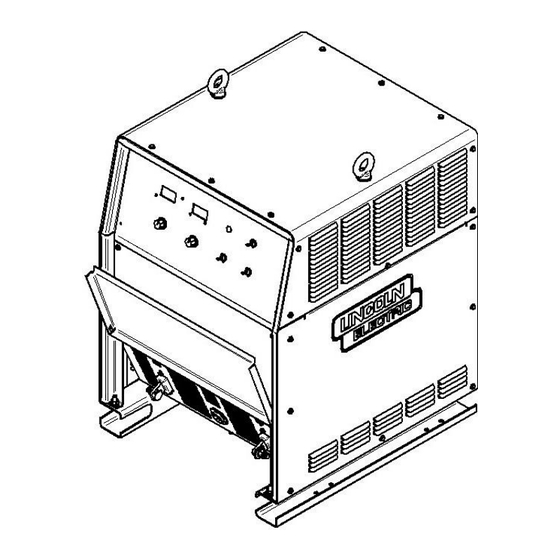
MAIN PARTS LIST FIGURE H.1 MAIN PARTS LIST Ⅱ POWERPLUS... - Page 78 MAIN PARTS LIST Ⅱ POWERPLUS...
- Page 79 MAIN PARTS LIST Ⅱ POWERPLUS...
- Page 80 MAIN PARTS LIST TABLE H.1 MAIN PARTS LIST QTY USED PER ITEM DESCRIPTION PART NUMBER PRODUCTION UNIT RIGHT SIDE PANNEL L13195 EYEBOLT S26786 TOP ROOF L13196-1 SIGNAL LAMP ASSEMBLY S27278-1 METER BOARD ASSEMBLY 9EL10952-1 CASE FRONT WELDED ASSEMBLY G5894-1 POTENTIOMETER ASSEMBLY G6235-3 KNOB T13639-6...
- Page 81 MAIN PARTS LIST QTY USED PER ITEM DESCRIPTION PART NUMBER PRODUCTION UNIT AUXI. TR (FOR MACHINE CODE 76075) M21437-4 AUXI. TR (FOR MACHINE CODE 76074) M21437-5 TRANS. LIFT BRACKET A G6001-2 FAN MOTOR M20713 CAPACITOR (SUPPLIED WITH MOTOR) S27301 TRANS. LIFT BRACKET B M21478-2 FAN BRACKET WELD ASSY L13199-1...
- Page 82 MAIN PARTS LIST QTY USED PER ITEM DESCRIPTION PART NUMBER PRODUCTION UNIT CONTACTOR ASSEMBLY L13325-2 INPUT CABLE BRACKET M20720-6 HEATSINK AND SCR ASSEMBLY L13326-2 WITH BRACKET Not Shown WIRE FEEDER CONTROL CABLE ASSEMBLY G6235-6 Not Shown SCR HARNESS G6235-4 HIGH VOLTAGE HARNESS Not Shown G6235-2 FOR CONNECTING WITH CONTACTOR, POWER...
- Page 83 NOTE Ⅱ POWERPLUS...
- Page 84 • World’s Leader in Welding and Cutting• THE SHANGHAI LINCOLN ELECTRIC COMPANY No. 195, Lane 5008, Hu Tai Rd. Baoshan, Shanghai, PRC 201907 www.lincolnelectric.com.cn Ⅱ POWERPLUS...
Need help?
Do you have a question about the POWERPLUS II 500 and is the answer not in the manual?
Questions and answers