
Subscribe to Our Youtube Channel
Related Manuals for Linear 2GIG Go!Control GC2

Summary of Contents for Linear 2GIG Go!Control GC2
- Page 1 USER GUIDE Go!Control WIRELESS SECURITY SYSTEM WARNING: OWNER’S INSTRUCTION NOTICE Not to be removed by anyone except occupant...
-
Page 2: Table Of Contents
CONTENTS System Overview....3 24 Hour EmergencyButtons....21 Features ....... .3 System Trouble Alerts. - Page 3 Go!Control Wireless Security System | User Guide Dialer Delay ......40 2-Way Voice......41 TelephoneRemote Control Answer .
-
Page 4: System Overview
SYSTEM OVERVIEW This system provides three forms of protection: burglary, fire, and emergency, depending on the options set by your installer. The system consists of the Control Panel with a color touch screen, wireless sensors that provide perimeter and interior burglary protection, and wireless smoke and carbon monoxide detectors. In addition, optional remote control key fobs, wireless panic buttons and keypads may have been provided or installed. The system monitors all protection “zones” and the system’s status. The Control Panel displays monitoring information and controls the alarm siren. Your system may also have been setup to send alarm and status reports to a Central Station and has the capability for 2‐way voice communications with the alarm monitoring operator. FEATURES Following is a list of standard features and options that can be included in your system. Ask your installer which options are available to you and check the boxes that apply. • Stay and Away arming modes: Stay Mode arms the system perimeter only and is used typically at night when the premises are occupied. Away Mode arms the system perimeter and interior; it’s used when the premises are unoccupied. • 32 user‐unique 4‐digit codes to operate the system: The system supports one Master User Code that can assign and maintain the other User Codes. • One of the 32 User Codes functions as a Duress User Code. Controlling the system with this code gives the appearance of normal operation, but using it secretly sends a “duress” report to the Central Station to initiate a silent alarm call for help. • Voice announcements from the Control Panel: The system has a vocabulary of descriptive words that can be assigned to sensors so each has a unique announcement such as “front door” or “bedroom window” if desired. • Home automation with the built‐in Z‐Wave controller for remote controlling Z‐Wave enabled home appliances (optional feature). • Alarm history with system event log: Each alarm and system alert is logged into the system’s memory. These events can be displayed and reviewed at the Control Panel or remotely by the Central Station. • Real time clock and calendar shows on the system’s display and is used to time stamp items in the event log. NOTE: If installed in a commercial location, this Control Panel is intended for burglary protection only (and not for fire protection) and that burglary protection is limited to ... -
Page 5: Basic Operation
Go!Control Wireless Security System | User Guide BASIC OPERATION User Codes The system installer has already Following are general operational concepts programmed a Master User Code for your that your system supports. Understanding system. This code can be used to control the these concepts will help you to use your system as well as assign and change the security system to its fullest extent. other user codes. The Master User Code can also access several system setup settings in Sensor Types/Zones the User Toolbox. The system’s wireless sensors have been assigned to selected “types” (often called Alarms “zones”). The sensor type determines how When an alarm occurs, the Control Panel’s and when the system will react to a signal siren and an external siren (if installed) from the sensor. Some sensors are armed 24 sounds for a preset time. During alarms and hours a day, other sensors are only armed after disarming, the alarm history button when the system is armed. displays all the alarms that have occurred, and which sensors were involved. The alarm Smoke, Heat, and Freeze history clears the next time the system is ... -
Page 6: Control Panel Features
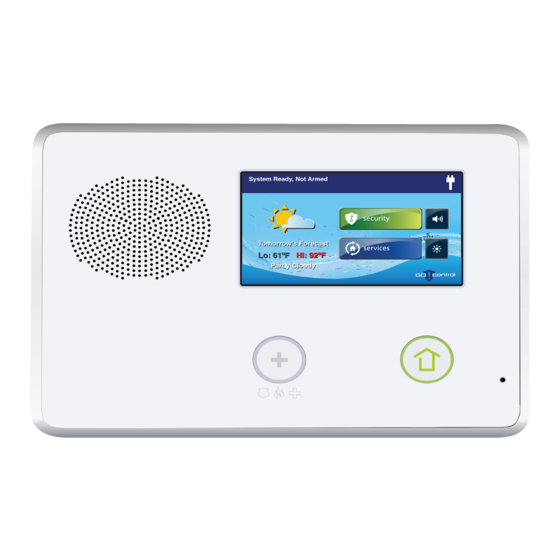
System Overview CONTROL PANEL FEATURES See the table below for full descriptions of Control Panel Features. A Alarm Sounder and Speaker Sounds all system local alarms, voice prompts, system sounds, and audio for 2‐way voice communications with the Central Station B Color Display with Shows all system information, status, programming, and functions as Touchscreen the keypad. Display cycles clock, calendar, and weather (press manually to change) C Microphone For voice communication with the Central Station D Emergency Button/Indicator Lights White when enabled for emergency alarms. Flashes White during emergency alarms E Home Button/Indicator Sensor Status Lights Green when all sensors are closed (ready to arm) Not lit when any sensor is open (not ready to arm) Arming Status Lights Red when system is armed Flashes Red during the Entry Delay Alarm Memory Flashes Red during an alarm Flashes Red after an alarm while system is still armed Power Outage Flashes White during power outage (system on battery backup) Flashes Green when all sensors are closed (ready to arm) Flashes Orange when any sensor is open (not ready to arm) Flashes Red while system is armed ©2013 2GIG Technologies Inc. All Rights Reserved. -
Page 7: Main Display Screens
Go!Control Wireless Security System | User Guide MAIN DISPLAY SCREENS system status and arming buttons for Stay and Away. Optional check boxes for Entry The Control Panel is programmed and Delay and Silent Exit are displayed. operated using the color touch‐screen display. The display shows various buttons, indicators, and text to guide and inform you. The top bar on the display shows the current system mode, scrolling text of any pending alerts, and system status icons. Home Screen The Home Screen shows system status with icons to indicate system conditions. It also displays the time and date. The Home Screen Menu Screen has Security, Services, Silent Control and The Menu Screen shows the system status Display Off buttons. across the top of the screen and 3 main buttons: The Arm button and Toolbox button are always displayed. If the emergency option is set, an Emergency button is also displayed. Chime and Voice check boxes are also displayed. TIP: Services is a system option for controlling Z‐Wave devices, if not active, the button is not displayed. •... -
Page 8: Burglary Protection
BURGLARY PROTECTION When your system was setup by your installer, wireless sensors were placed to monitor specific doors and windows. The installer selected these doors and windows as likely places where an unlawful intrusion might occur and could be detected. Each sensor was programmed to have the system react in a specific way. See “Installer Programmed Options” on page 38 for specifics about each sensor. Some sensor types such as smoke detectors, carbon monoxide detectors, panic buttons, etc. are always active and can trigger an alarm at any time. Other sensors on protected doors and windows are part of the burglary protection part of the system, and can be turned on or off. Turning on the burglary protection part of the security system is called “Arming the System”. The burglary protection part of the system can be armed in two modes: Stay Mode or Away Mode. SAMPLE FLOOR PLAN Refer to the floor plan below. It shows a typical residential installation and the various types of wireless sensors and their functions. Front and side door sensors have Exit/Entry delay SMKE Smoke detector Side and main garage door sensors have Exit/Entry delay Carbon monoxide detector Control panel Glass break sensor Door/window sensor Wireless keypad Motion detector External siren This security system is in compliance with UL 681 (Burglar and Holdup Alarm NOTE: Systems) and UL 827 (Central Station Alarm Services). ©2013 2GIG Technologies Inc. All Rights Reserved. -
Page 9: Sensor Status
Go!Control Wireless Security System | User Guide SENSOR STATUS The security system constantly monitors all of the sensors attached to the protected doors and windows in your home or business. The Control Panel knows if each door or window with sensors is open or closed. The open or closed condition of the protected doors and windows is called the sensor status. For maximum security, all the doors and windows on your premises should be closed when you leave the building. In some cases, such as when using the security system when you stay at home, you may want to leave some doors or windows open. The system recognizes bypasses to resolve the open doors or windows. See "Manually Bypassing or Un‐bypassing Sensors" on page 10. NOTE: Before you can arm the system, you must close or bypass all doors and windows with sensors. NOTE: If installed in a commercial location, this Control Panel is intended for burglary protection only (and not for fire protection) and that burglary protection is limited to mercantile premises and not bank vaults. CHECKING THAT ALL SENSORS ARE CLOSED In most cases, you will be arming the security system with all of the sensor‐protected doors and windows closed. The Control Panel provides easy ways to verify that all the sensor‐ protected doors and windows are closed before arming the system: • The Home button lights green when all perimeter sensors are closed. The Home button is not lit if any perimeter sensor is open. Open interior sensors do not change this indication. •... -
Page 10: Viewingeach Sensor's Status
Burglary Protection VIEWING EACH SENSOR’S STATUS The Control Panel will also show you which sensor‐protected doors and windows are open. Your installer has programmed descriptive names for each sensor‐protected door and window. The Control Panel’s color display will show the names of which doors and windows are open. • The top of the display on the Home, Security, and Menu Screens sensor status. See “System Status Icons” on page 23. Pressing the Status button also displays a list of open sensors and general system status and alerts. A The Status Bar shows the system mode and shows system status icons. See “System Status Icons” on page 23. B The Arm button on the security and menu screens lights green when all perimeter sensors are closed. The Arm button lights orange if any perimeter sensor is open. C The Home button lights green when all perimeter sensors are closed. The Home button is not lit if any perimeter sensor is open. D The icon displayed shows that an interior sensor is open. Other icons can appear here as well. See “System Status Icons” on page 23. Dealing with a sensor False Alarm The Control Panel reports alarm conditions on all sensors when armed both visually (on the status bar, and through a system alert icon) and audibly (through voice and chime announcements). There are times, though rare, that an sensor will send an alarm condition to the Control Panel when no alarm exists. The conditions of a false alarm vary depending on the type of sensor and how that sensor communicates with the Control Panel. • Perform a System, Sensor, and Panel Test to find any false alarm conditions. See "System Test" on page 31. See "Sensor Test" on page 31. See "Panel Test" on page 32. -
Page 11: Sensor Bypassing
Go!Control Wireless Security System | User Guide SENSOR BYPASSING NOTE: Bypassed sensors offer no protection and cannot cause an alarm. Use bypass if Before the system can be armed, all you want to arm your system with one or protected doors and windows must be more sensors open and intentionally closed or bypassed. You can bypass open unprotected. sensors on protected doors or windows before arming the system. When a sensor is Force Bypassing Sensors bypassed, the system ignores that the door If any sensors are open when the Arm or window is open. There are two types of button is pressed, the Control Panel displays sensor bypasses available: the bypass sensor screen. When the system • Forced is disarmed, the force bypassed sensors are • Manual returned to normal. In some cases (such as when using the With one or more perimeter sensors security system for protection when staying open, press Arm from the Security or at home) it may be desirable to leave some Menu Screen. -
Page 12: Stay Mode
Burglary Protection STAY MODE opened. Un‐checking this option box removes the delayed alarm trigger from all Stay Mode is for arming the system when sensor‐protected doors programmed for people are staying on the premises. Stay delay, causing those entrances to instantly Mode arms the sensor‐protected perimeter trigger the alarm if they are opened in Stay doors and windows while not arming the Mode. interior motion sensors or other interior doors. This allows the premises to be Quick Exit in Stay Mode occupied while the system is partially armed. A programmable option, called Quick Exit Stay Mode is used mostly for arming the may be displayed on the Security Screen system during the evening hours after while the system is armed in the Stay Mode. everyone is inside and no one is expected to Pressing the Quick Exit button starts a timer enter or leave. to allow someone to exit or enter through a When the system is armed in Stay Mode, you sensor‐protected door programmed for can move about the premises without delay without having to disarm the entire triggering the burglary alarm. All the interior system. When the delay timer runs out, the burglary protection is off. But, if a sensor‐ system returns to the normal Stay Mode. protected perimeter door or window is opened, an alarm occurs. -
Page 13: Armingto Stay Mode
Burglary Protection Arming to Stay Mode entry perimeter doors as instant, un‐ check the Entry Delay option button. Use Stay Mode to arm the system when anyone is at home. Stay Mode normally has Press Stay to arm the system. an Entry Delay so a user with a User Code NOTE: To arm the system, you may need to can re‐enter without causing an alarm. enter a User Code if your installer has Close all protected perimeter doors and turned off the system’s Quick Arming windows before arming. feature. Verify that the button on the Control The system will arm and shows the Exit Panel is lit green indicating that the Delay counting down. When the Exit system is ready to arm. The Security Delay expires, the system is fully armed button and Arm button on the display is in the Stay Mode. green when all sensors are closed. AWAY MODE Away Mode is for arming the system when everyone is leaving the premises. Away Mode arms all sensor‐protected perimeter doors and windows, interior motion sensors, interior glass break sensors, and any other sensor‐protected interior doors. The premises must be unoccupied while the system is armed. Away Mode is typically NOTE: If you desire to arm the system ... -
Page 14: Exit Delay Restart
Go!Control Wireless Security System | User Guide When arming the system in timer to allow someone to exit or enter Away Mode, an Entry Delay through a sensor‐protected door check box is shown on the programmed for delay without having to Arming Screen. By default, disarm the entire system. When the delay this option is checked, so the timer runs out, the system returns to the programmed delay doors allow time for normal Away Mode. disarming the system after the door is TIP: If interior sensors are installed in the opened. If you un‐check this box, the system in certain areas, do not violate delayed alarm trigger is removed from all those sensors when using the Quick Exit sensor‐protected doors programmed for feature in Away Mode. delay. Those entrances instantly trigger an alarm if they are opened in Away Mode. Auto Stay Mode NOTE: With the Entry Delay disabled, you The system may have been programmed by must remotely disarm the system with a the installer for Auto Stay Mode. If this wireless key fob before entering. option is on and the system is armed in Away Mode, if an exit/entry delay sensor is not ... -
Page 15: Disarmingthe System
Burglary Protection button and Arm button on the display NOTE: When the system is armed in the will also be green when all perimeter Away Mode, beeps sound during the Exit sensors are closed. If the icon is Delay (faster beeps during the last 10 displayed on the status bar, an interior seconds). sensor is open, be sure to close or manually bypass the interior sensors or DISARMING THE SYSTEM an alarm will occur. To stop the Control Panel from triggering To arm the system quietly without burglary alarms, the system needs to be sounding any announcements, press the disarmed. Disarming turns off the burglary button before performing the next detection part of the system for sensors that steps: are not 24‐hour sensors. Disarming also • From the Arming screen select the stops any type of alarm in process. Silent Exit check box • During the Exit Delay, press Silence From the Security Screen, or the Menu Screen, press Arm. If there are any open perimeter door or window sensors, the Bypass Screen appears. Close all the sensors displayed or press Bypass All to force bypass the displayed sensors. Disarm the system from Stay Mode before ... -
Page 16: Disarmingfrom Stay Mode
Go!Control Wireless Security System | User Guide Disarming from Stay Mode Delayed sensors start the Entry Delay to allow time to disarm the system. Instant Disarm the system from Stay Mode before sensors trigger the alarm right away. Most exiting the premises. sensors trigger the alarm siren, some From the Security Screen, press for sensors may be set to trigger a silent alarm Silent Control. without sounding the siren. From the Security Screen or the Menu Screen, press Disarm. This action Burglary Alarm Siren displays the Disarm Code Screen. If there is a burglary alarm tripped while the system is armed, the Control Panel sounds the alarm siren for a preset time (see "Installer Programmed Options" on page 38). After the time expires, the siren will stop sounding. The system limits the number of times a sensor can re‐trigger an alarm while the system is armed. The setting is one to six times per sensor, per arming period (see The left side of the screen shows any "Installer Programmed Options" on page 38). events that have occurred while the ... -
Page 17: Optional2 Way Voice Communications
Burglary Protection KEY FOB ARMING AND The alarm memory automatically clears the next time the system is armed. You can also DISARMING check the Clear Alarm History button and Your system may be equipped with one or press Ok to manually clear the alarm more wireless key fobs. Up to eight key fobs memory (24‐hour fire and CO sensors that can be used to control the system remotely. are still violated remain in alarm memory). Each key fob has four buttons and can perform five functions. A User Code is not Optional 2-Way Voice required when arming or disarming the Communications system with a wireless key fob. 2‐way voice communications provides a There are several key fob options that can be method for alarm verification and can set by the installer. See "Installer provide emergency assistance. The Control Programmed Options" on page 38. Panel contains a built‐in microphone that can monitor sounds around the area of the Key Fob Arming to Stay Mode Control Panel. The built‐in microphone and • To arm the system to Stay Mode using a ... -
Page 18: Key Fob Auxiliary
Go!Control Wireless Security System | User Guide WIRELESS KEYPAD NOTE: If an emergency alarm is triggered by a key fob, it cannot be stopped using the ARMING TO AWAY MODE key fob Disarm button. The alarm must To arm the system to Away Mode using a be canceled at the Control Panel. wireless keypad, enter a User Code. Key Fob Auxiliary Press the Away button. • To trigger the Control Panel’s auxiliary If Quick Arming has been programmed output, press the Auxiliary button. by your installer, just press the Away button If you use the Auxiliary button, the auxiliary output controls the _________________... NOTE: If there are open perimeter doors or windows, the system does not allow Arming to Away Mode with a wireless WIRELESS KEYPAD keypad. All open sensor‐protected doors ARMING AND DISARMING and windows must either be closed or ... -
Page 19: Smoke, Heat And Freeze Protection
SMOKE, HEAT AND FREEZE PROTECTION Your system should be installed with Smoke, If flames and smoke are present, yell Heat, and Freeze Alarms as well as Carbon “Fire” to alert everyone else. Monoxide Detectors as a part of an overall Evacuate all occupants from the fire, heat, and gas protection system. Fire premises and call your local Fire protection is active 24 hours‐a‐day, 365 days Department from a safe location. a year. In the event of a fire or poisonous CO gas If no flames or smoke are apparent, emergency, the installed smoke or carbon investigate the possible causes of the monoxide detector automatically activates alarm. your security system. Not only will the fire Go to the Control Panel and enter your alarm itself emit a loud sound, the Control User Code to stop the fire sounder and Panel emits an intermittent and loud horn sirens. on an external sounder (if an external sounder has been installed). The fire alarm Review the "Alarm Memory" on page 15 sound continues until the timer expires on to determine which sensor caused the the Fire Alarm or until you enter a User Code alarm. at the Control Panel. Go to the sensor and look for a possible reason the sensor tripped. If the Alarm Sounds Correct the condition that caused the ... -
Page 20: Recommended Fire Alarm Locations
Smoke, Heat and Freeze Protection RECOMMENDED FIRE ALARM LOCATIONS In the United States, this equipment shall be installed in accordance with the National Fire Alarm Code, ANSI/NFPA 72, (National Fire Protection Association, Batterymarch Park, Quincy, MA 02269). Printed information describing proper installation, operation, testing, maintenance, evacuation planning, and repair service is to be provided with smoke detectors and alarms. National Fire Protection Association Standard #72 The National Fire Protection Association’s (NFPA) Standard #72 recommends the following placement for smoke detectors: Early warning fire detection is best achieved by the installation of fire detection equipment in all rooms and areas of the household. The equipment should be installed as follows: • Install a smoke detector outside each separate sleeping area, in the immediate vicinity of the bedrooms and on each additional story of the family living unit, including basements and excluding crawl spaces and unfinished attics. Also install smoke detectors in the living room, dining room, bedrooms, kitchen, hallway(s), finished attics, furnace room, utility and storage rooms, and attached garages. A Mount a smoke alarm between the sleeping area and the rest of the family unit. B In family units with more than one sleeping area, mount a smoke alarm to protect each sleeping area. C Example of a residence that has required and optional areas for smoke alarms. D For houses with multiple stories, mount a smoke alarm on each story. Indicates an optional smoke alarm if a door is not provided between the Living and the ... -
Page 21: Emergencyaction Plan
Go!Control Wireless Security System | User Guide Where NOT to Mount the Alarm • Directly above a sink, cooker, stove or oven • Do not locate alarm within 5 feet (1.5 m) of any cooking appliance • Next to a door or window that would be affected by drafts (extractor fan or air vent) • Outside • In or below a cupboard • Where air flow would be obstructed by curtains or furniture • Where dirt or dust could collect and block the sensor • Where it could be knocked, damaged, or inadvertently removed Fire‐warning equipment for residential occupancies are capable of protecting about 50% of the occupants in potentially fatal fires. Victims include the elderly, children, and the physically or mentally impaired. Victims include any person that cannot escape even when warned early enough that escape should be possible. For these people, other strategies such as protection‐ in‐place or assisted rescue or escape would be necessary. • Studies show that Smoke/Heat/Freeze Alarms may not awaken all sleeping individuals. It is the responsibility of individuals in the household that are capable of assisting others to provide assistance to those who may not be awakened by the audible alarm or those who may be incapable of safely evacuating the area unassisted. • A battery‐powered alarm must have the specific battery type installed, be in good ... -
Page 22: Emergency Functions
EMERGENCY FUNCTIONS 24-HOUR EMERGENCY BUTTONS Three 24‐hour emergency functions are available on the Control Panel: • Panic • Fire • Emergency You can activate emergency functions using the Control Panel as well as wireless sensors, wireless keypads or from portable pendant devices such as the panic button remote. The button displays the emergency screen. Just pressing the button does not trigger an alarm. During the installation, your installer programmed the emergency buttons that are displayed on the Emergency Screen. If, however, no emergency functions are available, an information screen displays. To see which emergency functions are available on your system, press the button. In the event of an emergency, press and hold the emergency button for at least 2 seconds to activate the alarm. A If emergency functions are available, the Emergency button is a solid white lighted button. B To display the Emergency Screen, press the Emergency button. C The Emergency Screen. D The Emergency Screen displays the emergency options that are available on your system. Panic The panic (or police) button sends an immediate panic report to the Central Station. During installation, the installer either set the system to sound the siren when the button is pressed, or to not sound the siren, but to trigger a silent alarm. Fire The Fire button send an immediate fire report to the Central Station. The Control Panel sounds the fire horn when the button is pressed. Emergency The emergency button sends an immediate report to the Central Station. The Control Panel ... -
Page 23: System Trouble Alerts
SYSTEM TROUBLE ALERTS View the Current Trouble The system continually polls wired sensors, wireless sensors and the Control Panel itself Alerts to ensure optimal operating conditions at all To display all current trouble alerts, press times. If trouble is detected, the system the Trouble Alert Icon. alerts you. View the listed trouble events. If there The system monitors the following are more than 3 alerts, use the ↑ and ↓ conditions among others: arrows to scroll through the list. • AC power to the Control Panel • The telephone line (optional) • The cell telephone connection (if used) • The Control Panel’s backup battery • The sensor’s batteries • Sensor supervisory status (if used) • External sounder connection • Sensor radio reception and sensor tampering (sensor’s case opened) when disarmed • Control Panel tampering (panel’s case After viewing the trouble events, press ... -
Page 24: System Status Icons
System Trouble Alerts SYSTEM STATUS ICONS Test Mode Icon When the system is placed in System Test The top part of the Control Panel’s display is Mode, the test mode icon will flash in the the status area that shows the following: status bar of the display during the testing. • Current system mode • Sensor status • Current trouble alerts Special icons are used to visually TIP: show your system’s current Remote Access Icon condition. When the system is being remotely accessed by using an optional TS1 Wireless Keypad, Status Icon Area the Remote Access Icon is displayed. Radio Modem Icon If the system’s optional Cell radio modem is installed, the cell radio icon is displayed on the status bar while the cell radio is being used to update software or add features. AC Power Icon The AC power icon displays whether the ... -
Page 25: Messaging
MESSAGING SYSTEM MESSAGES right corner. Urgent messages display a yellow message icon with an attention Your security system supports receiving symbol in the upper right corner. Emergency messages from the Central Station. The messages display a red message icon messages can be about system upgrades, with the bell symbol in the upper right additional services, special regional weather corner. alerts, etc. The messages can be sent for all system users to read, or as confidential READING MESSAGES messages that only the Master User can When a message icon appears on your Home read. Messages can be tagged by the sender Screen, do the following: in the following manner: Press the message icon button. The • Standard (blue message icon) message list displays. The status bar shows the number of messages in memory, number of unread, and number of priority messages. Unread messages display in bold. Use the ↑ or ↓ arrows to scroll through the message list. Press the message line itself to read the message. • Urgent (yellow message icon) •... -
Page 26: Readingcon Dential Messages
Messaging READING CONFIDENTIAL To display the Message Filter Screen, press Filters. MESSAGES NOTE: When a confidential message is sent to the Control Panel, only the Master User with the Master User Code can read the message. When a confidential message appears, the Master User should do the following: Press the message line on the message list. If the message is a confidential message, the Code Entry Screen Check or Un‐check the types of messages appears. to display. To check all types of messages, press All. To return to the message list, press Back. The filters will reset when the following occurs: • You select All Types • Your message reviewing is over • The system displays the Security Screen Sorting Messages On the Code Entry Screen, Enter the To select the order in which messages are Master User Code. Regular User Codes displayed on the message list, use the are not accepted. Message Sort Screen. To display the Message Sort Screen, press Sorts. View the displayed message. As detailed in "Reading Messages" on ... -
Page 27: Remote Control By Telephone
REMOTE CONTROL BY TELEPHONE TELEPHONE REMOTE For security purposes, if 2 attempts using 2 telephone calls to enter a User Code You can control your system remotely using a within a 5 minute time frame fail to standard telephone if your system was enter a valid code, the system installed with a POTS module. Remote disconnects and does not respond to control is performed by calling the system telephone commands for 30 minutes. and responding to spoken questions from After the system has accepted your User the system. By pressing certain telephone Code, it announces the system status, keys, you can do the following: then announces the remote command • Arm the system options. • Disarm the system • Bypass sensors The system waits up to 60 seconds for • Query system status each remote command before NOTE: At the time your system was automatically disconnecting. If you installed, your installer needed to enable already know the remote command the optional remote control by telephone key number, you can enter it telephone feature. Otherwise you will be ... -
Page 28: System Toolbox
SYSTEM TOOLBOX USER MANAGEMENT Enter the Code again to confirm the code and press Ok. The system installer has programmed a A confirmation screen appears. Press Ok. Master User Code for your system. This code can be used to control the system, as well as User Code Validity assign and change the other 31 User Codes After the Confirmation Screen Appears and and User Code access options. The Master you click Ok, the User Codes Access Option User Code can also access several system Screen appears. The three options setup settings in the Toolbox. determine when the User Code that you just NOTE: The other 31 User Codes are entered is valid. Select one of the three restricted from accessing settings in the options: Toolbox. • Always • Never User Code Setup • By Schedule IMPORTANT: Only the person with the • Select Always to set this User Code Master User Code can add or change the ... -
Page 29: Recurringuser Access Schedules
Go!Control Wireless Security System | User Guide You can also create a new user schedule Press the left and right time buttons to from the Edit Schedule screen. set the start and end times that this User Code is valid on that date. The User Access Schedules Screen displays all current schedules for the Press Ok to accept the schedule, or User Code. Cancel to return to the Schedule Type Screen. To add a new schedule, press Add Schedule or to edit a schedule, press an Date Range User Access existing schedule. Schedule You can select 1 of 3 Schedule types: For the Schedule type, select Date • Recurring Range. • Date • Date Range • Recurring applies to the days of the week and time period that this User Code is valid. • Date applies to a single specific date ... -
Page 30: Changing A User Code
System Toolbox On the User Access Schedules Screen, To confirm the User Code, enter the Pin select the schedule to delete. again. Press Ok. A confirmation screen appears, showing that the User Code was changed. Press Deleting a User Code To delete a User Code from the User Management Screen, press the User button. Press Delete. On the Schedule Type Screen press A confirmation screen appears to verify Delete. that you really want to delete the User A confirmation screen appears to verify Code. If Ok, press Delete User or press that you really want to delete the User Cancel to return to the User Codes Access Schedule. If Ok, press Delete Access Option Screen. Schedule or press Cancel to return to the A confirmation screen appears displaying User Access Schedule Screen. the User Code that was deleted. Press A second screen confirms that the schedule was deleted. Press Ok. Changing a User Code From the User Management Screen, press the User button to change the User Code. Ensure that the currently selected User Code (or Pin number) appears, and press ... -
Page 31: Secret Duress Button
Go!Control Wireless Security System | User Guide entry screen. Enter the Duress User Code Setting the Duress User Code and a silent duress report is sent to the On the User Management Screen, press Central Station and they will dispatch help. the User 8 (Duress) button. The system remains disarmed. A confirmation screen appears: Press Create Duress User. SYSTEM HISTORY The Control Panel keeps a log of system events in the order in which they occur. Each event is marked with the date and time that the event occurred. To make reading the log easier, the system history display can be filtered to show selected events only. The events that can be filtered for the system history log display are: • Arm or Disarm of the system Enter a four‐digit code for the new • Bypasses of sensors (force bypasses and Duress User Code and press Ok. manual bypasses) To confirm the Duress User Code, enter • Alarms (alarms are displayed with a red the Code again and press Ok. -
Page 32: System Test
System Toolbox To choose the events to display, press From the Toolbox Screen (1 of 3), press Filters. System Test. Select the events to display with the Sensor Test check boxes. Press All to select all the check boxes, or None to clear all the When each sensor is tested, the Control check boxes. Panel does the following: Press Ok when finished. • Beeps and announces the sensor’s name • Green bar lights on the display by the sensor name SYSTEM TEST • Signal bars light green to show the Even though your security system is self‐ strength of that sensor’s wireless signal monitoring, it is still important to regularly NOTE: Start and stop test reports are sent to test the system manually. The System Test is the Central Station. used to test each of the sensors in the system. The Master User Code is required to From the list of sensors, choose each test the system. While the system is in test sensor (Use the ↑ and ↓ arrows to mode, a “T” icon blinks on the upper right of scroll through the list). the display. Go to each sensor listed, and trigger it. •... -
Page 33: Panel Test
Go!Control Wireless Security System | User Guide When all sensors have been tested. A To access the Toolbox, enter the Master User Code. confirmation screen appears. Use the ← and → arrows to select Panel Test Toolbox Screen (3 of 3). The panel test checks the Control Panel’s On the Toolbox Screen (3 of 3), press indicators and sounder. Telephone Test. A list of panel tests appears on the To begin the test enter the Master User Code again. Panel Test Screen. Use the ↑ and ↓ arrows to scroll through the list. Press each test button and answer Yes or No to the test question. Press Ok when all panel questions have been answered. A confirmation screen appears. To exit System, Sensor, and Panel Testing, press Ok. The system displays the Telephone Test Telephone Test Status Screen. The top part of the screen If your security system is connected to shows each function that is being tested. your telephone line it can communicate Use the ↑ and ↓ arrows to scroll with the Central Station using your through the status messages. The ... -
Page 34: Chime Options
System Toolbox IMPORTANT: Test your Security System The chime and voice TIP: weekly to ensure continued protection announcements only sound while and proper system operation. the system is disarmed. You can test the cellular radio connection At the time of installation, the installer using the Toolbox. programs each sensor’s chime option. The person with the Master User Code can From the Home Screen, press Security. change the chime options for each sensor to From the Security Screen, press Menu. further customize the system as desired. From the Menu Screen, press Toolbox. To access the Toolbox, enter the Master User Code. To select the Toolbox Screen (3 of 3), use the ← and → arrows. On the Toolbox Screen (3 of 3), press Cell Phone Test. As a global system option, the TIP: chimes for all the system’s sensors can be turned on or off using the Chime check box on the Menu Screen. To setup the chime options individually for each sensor, do the following: To begin the test enter the Master User From the Home Screen, press Security. Code again. From the Security Screen, press Menu. The system displays the test status screen. The top part of the screen shows Note the Chime and Voice check boxes ... -
Page 35: Brightness/Volume
Go!Control Wireless Security System | User Guide that can chime and the option currently From the Menu Screen, press Toolbox. set for the sensor. Enter the Master User Code to access the toolbox. To change the sensor’s chime options, press the sensor button. From the Toolbox Screen (1 of 3) press There are 14 chime options for TIP: Brightness/Volume. You can set the each sensor. brightness using the top bar. Adjust the level from 1 to 12 using the buttons on each end of the bar. You can set the speaker volume for the chimes and announcements on the bottom bar. Adjust the level from 1 to 12 using the buttons on each end of the bar. The volume setting does not effect the alarm sounder volume. When you are finished, press Ok. Check the option that you want for the sensor, then press Ok. BACKLIGHT TIME-OUT When you are finished, press Back. The backlight time‐out sets the length of Chime Options time that the display stays lit after use. You 1 Disabled Ding‐dong with Voice #3 can adjust the backlight to 30 seconds, 1, 2, ... -
Page 36: Displaycleaning
System Toolbox From the Toolbox Screen (2 of 3), press time. When the timer expires, the Backlight Time‐out. system returns to the Toolbox Screen. Choose one of the display backlight times and press Ok. DISPLAY CLEANING There is a special option for the Control Panel that enables you to clean the touch screen display. The option locks the display for 30 seconds so it can be cleaned without sensing any button presses. Clean the display with a dry, soft cloth. To lock the display for cleaning, do the following: From the Home Screen, press Security. From the Security Screen, press Menu. From the Menu Screen, press Toolbox. To access the toolbox, enter a valid User Code. From Toolbox Screen (1 of 3), press the → arrow. From the Toolbox Screen (2 of 3), press Clean Screen. The Display Cleaning Screen appears for 30 seconds. It shows the time remaining. The touch screen is locked during this ©2013 2GIG Technologies Inc. All Rights Reserved. -
Page 37: Touch Screen Calibration
Go!Control Wireless Security System | User Guide TOUCH SCREEN SET DATE AND TIME CALIBRATION The Control Panel has a built‐in clock and calendar. The Home Screen displays the time To calibrate the display, do the following: and date. The time and date are also used From the Home Screen, press Security. for the system history and event logs that From the Security Screen, press Menu. store data on system events. From the Menu Screen, press Toolbox. NOTE: During installation, your installer can set the system to automatically adjust for To access the toolbox, enter a valid User daylight saving time if it’s observed in Code. your location. From Toolbox Screen (1 of 3), press the → arrow. NOTE: The time and date are automatically set through the cellular radio by the From the Toolbox Screen (2 of 3), press Central Station if your Control Panel has Calibrate Touch Screen. a cellular radio installed. To set the date and time, do the following: From the Home Screen, press Security. -
Page 38: Displayfirmware Version
System Toolbox DISPLAY FIRMWARE VERSION To troubleshoot your system, you can check the firmware version that has been installed. To display the firmware version, do the following: From the Home Screen, press Security. From the Security Screen, press Menu. From the Menu Screen, press Toolbox. From Toolbox Screen (1 of 3), press the → arrow. From Toolbox Screen (2 of 3), press Version. When finished, press Back. ©2013 2GIG Technologies Inc. All Rights Reserved. -
Page 39: Installer Programmed Options
INSTALLER PROGRAMMED OPTIONS The installer can program different options Exit Delay to customize the installation. The options The Exit Delay begins immediately after listed below show the default settings and a arming the system. The delay gives you time check box or area to denote custom settings. to leave through the designated exit/entry door without setting off the alarm. During the Exit Delay beeps sound, and faster beeps Siren Run Time sound during the last 10 seconds. If there is a burglary, panic (police), or NOTE: Arming remotely does not start an emergency alarm, the Control Panel sounds Exit Delay. the siren for a preset time. After the time expires, the siren will stop sounding. • 60 Seconds is the default, or ________ (Auxiliary alarms run for an unlimited time.) For ________ Door 4 Minutes is the default, or the following: 8 Minutes Entry Delay 12 Minutes The Entry Delay begins when the designated 16 Minutes entry/exit door is opened while the system is ... -
Page 40: Quick Arming
Go!Control Wireless Security System | User Guide Quick Arming Auto Stay Quick Arming allows you to arm your system The Auto Stay option will change the arming without having to enter a User Code. When mode if no one exits after arming the system you press the Stay or Away button, the in Away Mode. When the system is armed in system will start to arm without requesting a the Away Mode the Exit Delay will begin. User Code. With the Auto Stay option on, if a designated exit/entry door does not open and close • during the Exit Delay, the system • will arm in the Stay Mode instead of the Away Mode. Quick Bypass • Normally sensors that are open at the time • the system is armed will require force bypassing by entering your User Code. The system can be set so a User Code is not Key Fob Arm/Disarm Sound required to bypass open sensors when the The system can be set so when it’s armed or ... -
Page 41: Key Fob Options
Go!Control Wireless Security System | User Guide Key Fob Options expires, will restart the Exit Delay timer, giving you the full length of time to leave The installer selects which options are again. The restart option only works once, enabled for each key fob (1‐8) used with the each time the system is armed. system. Refer to the table below for the options selected for your key fobs: • • Options 1 2 3 4 5 6 7 8 Arm without Exit Delay Allow key fob disarming Cancel Display Enable key fob auxiliary key A “cancel” message will be sent to the Central Station if the system is disarmed within a preset period of time after an alarm Options 1 2 3 4 5 6 7 8 is triggered. The system can be set to display ... -
Page 42: 2-Way Voice
Go!Control Wireless Security System | User Guide many cities impose when police respond to a false alarm. Your installer also can program the system for no dialer delay. NOTE: The dialer delay is also known as the abort window. It gives you time to disarm, but doesn’t delay the siren from sounding. Disarming during the abort window can display a cancel message depending on the Cancel Display setting (see "Cancel Display" on page 40). • 30 Seconds is the default, or ______ Seconds 2-Way Voice The system can connect with a Central Station operator so they can converse with people on the premises after an alarm. The 2‐way voice option allows communication to and from the Control Panel and the Central Station. 2‐way voice communications will occur after the system has made its alarm report. Your installer sets which sensors can trigger the 2‐way voice option. • • Telephone Remote Control Answer Your installer selects whether your system supports the remote telephone option or not. If the telephone remote control answer ... -
Page 43: Installer Specific Information
INSTALLER SPECIFIC INFORMATION User Codes Sensor Zones Master User Zone 1 Zone 2 User 2 Zone 3 User 3 Zone 4 User 4 Zone 5 User 5 Zone 6 User 6 Zone 7 User 7 Zone 8 User 8 Zone 9 (Duress) Zone 10 User 9 Zone 11 User 10 Zone 12 User 11 Zone 13 User 12 Zone 14 User 13 Zone 15 User 14 Zone 16 User 15 Zone 17 User 16 Zone 18 User 17... -
Page 44: Service Information
SERVICE INFORMATION Your local Alarm dealer is the person best qualified to service your alarm system. Be sure to set up a routine service schedule with your local Alarm installer. THIS EQUIPMENT MUST BE CHECKED BY A QUALIFIED TECHNICIAN AT LEAST EVERY 3 YEARS. Important Power Supply Notice The Control Panel is powered by a plug‐in power supply. In case the power supply becomes unplugged, be sure to plug the power supply into an un‐switched receptacle. Do not connect the power supply to a receptacle controlled by a switch. ©2013 2GIG Technologies Inc. All Rights Reserved. -
Page 45: Regulatory Information
REGULATORY INFORMATION FCC TELEPHONE RULES number of devices that may be connected to the line, as determined by the total RENs, AND REGULATIONS contact the telephone company to The FCC requires that this alarm dialer determine the maximum REN for the calling system not make more than 15 repetitive area. For products approved after July 23, dialing attempts to a single telephone 2001, the REN for this product is part of the number. There are no limitations when the product identifier that has the format US: calls are made sequentially to two or more AAAEQ##TXXX. The digits represented by the alternative numbers, or when these calls are ## are the REN without a decimal point (e.g., spaced 10 minutes apart to a single number. 03 is REN of 0.3). For earlier products, the The FCC Rules and Regulations do not REN is separately shown on the label. specify the re‐attempt period as this can If this equipment causes harm to the vary for specific applications. When setting telephone network, the telephone company this period, take into consideration local, will notify you in advance that temporary interstate, foreign and special network call discontinuance of service may be required. completion characteristics, network But if advance notice is not practical, the processing time, a sufficient number of rings telephone company will notify the customer and busy/don’t answer modes. as soon as possible. Also, you will be advised of your right to file a complaint with the FCC ... -
Page 46: Alarm Dialing Equipment
Regulatory Information Alarm Dialing Equipment New Services Notes to User The installation and/or monitoring company If your home has specially wired alarm shall be notified if new telephone service, equipment connected to the telephone line, e.g. DSL, is installed. ensure that the installation of any other non‐ alarm devices does not disable your alarm equipment. If you have questions about what will disable alarm equipment, consult your telephone company or a qualified installer. IMPORTANT: When programming emergency numbers or making test calls to emergency numbers remember the following: Remain on the line and briefly explain to the dispatcher the reason for the call. Perform such activities in the off‐peak hours, such as early mornings or later evenings. Follow the central station operator’s instructions for updated dialer programming, if re‐programming of the dialer is required. Alarm dialing equipment must be able to seize the telephone line and place a call in an emergency situation. It must be able to do this even if other equipment (telephone(s), answering system, computer modem, etc.) already has the telephone line in use. To do ... -
Page 47: Fcc & Industry Canada Regulatoryinformation
Go!Control Wireless Security System | User Guide blocked by radio signals that occur on or l’appareil ne doit pas produire de brouillage, near their operating frequencies, regardless et (2) l’utilisateur de l’appareil doit accepter of code settings. tout brouillage radioélectrique subi, même si le brouillage est susceptible d’en Unauthorized changes or modifications compromettre le fonctionnement. could void the user’s authority to operate the equipment. These limits are designed to provide reasonable protection against harmful Infrequently used radio links should be interference in a residential installation. This tested regularly to protect against equipment generates uses and can radiate undetected interference or fault. radio frequency energy and if not installed A general knowledge of radio and its vagaries and used in accordance with the should be gained prior to acting as a instructions, may cause harmful interference wholesale distributor or dealer, and these to radio communications. However, there is facts should be communicated to the end no guarantee that interference will not occur users. in a particular installation. If this equipment does cause harmful interference to radio or television reception, which can be FCC & INDUSTRY CANADA determined by turning the equipment off ... - Page 48 Regulatory Information extension cord). The customer should be This security system is in NOTE: aware that compliance with the above compliance with UL 681 (Burglar conditions may not prevent degradation of and Holdup Alarm Systems) and service in some situations. UL 827 (Central Station Alarm Services). Repairs to certified equipment should be made by an authorized Canadian maintenance facility designated by the supplier. Any repairs or alterations made by the user to this equipment, or equipment malfunctions, may give the telecommunications company cause to request the user to disconnect the equipment. Users should ensure for their own protection that the electrical ground connections of the power utility, telephone lines and internal metallic water pipe system, if present, are connected together. This precaution may be particularly important in rural areas. CAUTION: Users should not attempt to make such connections on their own, but should contact the appropriate electric inspection authority, or electrician, as appropriate. The Ringer Equivalence Number (REN) is an indication of the maximum number of devices allowed to be connected to a telephone interface. The termination of an interface may consist of any combination of devices subject only to the requirement that the sum of the RENs of all the devices not exceed five. L’indice d’équivalence de la sonnerie (IES) ...
-
Page 49: Important Notice
IMPORTANT NOTICE ALARM SYSTEM different level of the residence from the bedrooms, then they are less likely to LIMITATIONS waken or alert people inside the This security system can not offer bedrooms. Even persons who are awake guaranteed protection against burglary, fire, may not hear the warning if the alarm is or other emergencies. Any alarm system, muffled from a stereo, radio, air whether commercial or residential, is subject conditioner or other appliance, or by to compromise or failure to warn for a passing traffic. Finally, alarm warning variety of reasons. For example: devices, however loud, may not warn hearing‐impaired people or awaken • Intruders may gain access through deep sleepers. unprotected openings or have the technical sophistication to bypass an • While smoke detectors have played a key alarm sensor or disconnect an alarm role in reducing residential fire deaths in warning device. the United States, they may not activate or provide early warning for a variety of • Intrusion detectors (sensors) do not reasons in as many as 35% of all fires, work without power. Battery operated according to data published by the devices do not work without batteries, Federal Emergency Management with dead batteries, or if the batteries ... - Page 50 Important Notice sufficient warning to allow all occupants to escape in time to prevent injury or death. • This equipment, like other electrical devices, is subject to component failure. Even though this equipment is designed to last as long as ten years, the electronic components could fail at any time. The most common cause of an alarm system not functioning when an intrusion or fire occurs is inadequate maintenance. Although, installing an alarm system may make homeowners eligible for lower insurance rates, an alarm system is not a substitute for insurance. Homeowners, property owners, and renters should continue to act prudently in protecting themselves and continue to insure their lives and property. Control Panel Operating temperature and Humidity Ranges For optimal performance, the Control Panel should be operated under the following conditions: • Operating Temperature 0°C to 49°C (32°F to 120°F) • Humidity 0 – 90% Non‐condensing ©2013 2GIG Technologies Inc. All Rights Reserved.
-
Page 51: Limited Warranty
LIMITED WARRANTY This 2GIG Technologies product is warranted against defects in material and workmanship for twelve (12) months. This warranty extends only to wholesale customers who buy through 2GIG Technologies authorized distribution channels. 2GIG Technologies does not warrant this product to consumers. Consumers should inquire from their selling dealer as to the nature of the dealer’s warranty, if any. There are no obligations or liabilities on the part of 2GIG Technologies for consequential damages arising out of or in connection with use or performance of this product or other indirect damages with respect to loss of property, revenue, or profit, or cost of removal, installation, or reinstallation. All implied warranties, including implied warranties for merchantability and implied warranties for fitness, are valid only until the warranty expires. This 2GIG Technologies Warranty is in lieu of all other warranties expressed or implied. For warranty service call your local alarm installation and service professional at the contact information shown on the back cover of this User Guide. For technical support in the USA and Canada (855‐2GIG‐TECH (855‐244‐‐4832) For technical support outside of the USA and Canada: Contact your regional distributor Visit 2GIG.com for a list of distributors in your region ©2013 2GIG Technologies Inc. All Rights Reserved. - Page 52 YOUR LOCAL ALARM INSTALLATION AND SERVICE PROFESSIONAL: PN: 233485 Rev. A Copyright 2013 2GIG Technologies Inc. All Rights Reserved. www.2GIG.com...
Need help?
Do you have a question about the 2GIG Go!Control GC2 and is the answer not in the manual?
Questions and answers