Table of Contents
Advertisement
Quick Links
MODEL1835/MODEL1935/MODEL1945
SAFETY INSTRUCTIONS............................................................................................................. i
SYSTEM CONFIGURATION........................................................................................................ ii
EQUIPMENT LISTS .................................................................................................................... iii
1.
HOW TO INSTALL THE SYSTEM..................................................................................... 1-1
1.1
Display Unit ............................................................................................................... 1-1
1.2
Antenna Unit for MODEL1835 .................................................................................. 1-2
1.3
Antenna Unit for MODEL1935/MODEL1945............................................................. 1-9
2. CABLE CONNECTION ......................................................................................................... 2-1
2.1
Standard Connection ................................................................................................ 2-1
2.2
Data Signal Port ........................................................................................................ 2-2
3. HOW TO SET THE EQUIPMENT.......................................................................................... 3-1
3.1
How to Set the Language.......................................................................................... 3-1
3.2
How to Set the Purpose and Model .......................................................................... 3-2
3.3
How to Enter the Initial Settings ................................................................................ 3-3
4. OPTIONAL EQUIPMENT ...................................................................................................... 4-1
4.1
ARP Kit ARP-11 ........................................................................................................ 4-1
4.2
Connection of Buzzer and/or Remote Display .......................................................... 4-4
PACKING LISTS ...................................................................................................................... A-1
OUTLINE DRAWINGS ............................................................................................................. D-1
INTERCONNECTION DIAGRAMS ...........................................................................................S-1
Installation Manual
MARINE RADAR
Advertisement
Table of Contents

Related Manuals for Furuno 1935DISP


Summary of Contents for Furuno 1935DISP
-
Page 1: Table Of Contents
Installation Manual MARINE RADAR MODEL1835/MODEL1935/MODEL1945 SAFETY INSTRUCTIONS......................i SYSTEM CONFIGURATION......................ii EQUIPMENT LISTS ........................iii HOW TO INSTALL THE SYSTEM..................1-1 Display Unit ....................... 1-1 Antenna Unit for MODEL1835 .................. 1-2 Antenna Unit for MODEL1935/MODEL1945............. 1-9 2. CABLE CONNECTION ......................2-1 Standard Connection .................... -
Page 2: Safety Instructions
This is possible - Ask your FURUNO representative or Turn off the power at the mains switchboard dealer to provide this feature. before beginning the installation. -
Page 3: System Configuration
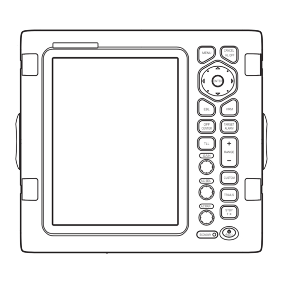
SYSTEM CONFIGURATIONS MODEL 1935 MODEL 1945 Antenna unit Antenna unit MODEL 1835 XN-10A-RSB-0070-064 XN-12A-RSB-0070-059 Antenna unit XN-10A-RSB-0070-064A XN-12A-RSB-0070-059A RSB-0071-057 XN-10A-RSB-0073-064 XN-12A-RSB-0073-059 RSB-0071-057A XN-10A-RSB-0073-064A XN-12A-RSB-0073-059A Display unit RDP-152 Heading sensor CANCEL MENU HL OFF Remote display ENTER Echo sounder GPS navigator TARGET CENTER ALARM... -
Page 4: Equipment Lists
EQUIPMENT LISTS Standard supply Name Type Code No. Comment Display unit RDP-152 w/Flush mounting sponge 02- 160-1201 (1 pc), Self-tapping screw 5x20 SUS304 (4 pcs.) Antenna RSB-0071-057 Unit for M1835 unit RSB-0071-057A XN10A-RSB-0070-064 Unit for M1935, 24 RPM XN10A-RSB-0070-064A XN10A-RSB-0073-064 Unit for M1935, 48 RPM XN10A-RSB-0073-064A XN12A-RSB-0070-059... - Page 5 Optional supply Name Type Code No. Comment Rectifier PR-62 For M1835 RU-3423 000-030-443 For M1935/1945 External buzzer OP03-21 000-030-097 Cable assy. MJ-B24LPF0010-100+R 000-147-880-12 For remote display, 10 m MJ-B24LPF0010-200+R 000-147-881-12 For remote display, 20 m MJ-B24LPF0010-300+R 000-147-882-12 For remote display, 30 m MJ-A10SPFW0001+R 001-074-600-10 Two-way cable for remote...
-
Page 6: How To Install The System
Display Unit Select a location for the display unit by following the information shown below. • The unit is waterproof, but FURUNO recommends that you install the display unit in a cabinet. • Keep the unit away from direct sunlight. -
Page 7: Antenna Unit For Model1835
How to install the display unit in a console Follow the procedure shown below to install the display unit in a console. 1. Prepare a hole in the location whose dimensions are 274 (W) x 252 (H) mm. 2. Make four pilot holes. See the outline drawing at the back of this manual for additional infor- mation. - Page 8 Antenna unit Antenna unit Antenna unit Antenna unit Normal position of the antenna unit on the sailboat and powerboat To reduce the electrical interference, do not run the antenna cable near other electrical equipment. Also do not run the cable in parallel to power cables. Make sure that you follow the compass safe distance shown on page i to prevent the interference to a magnetic compass.
- Page 9 Antenna unit: RSB-0071-057 Antenna unit: RSB-0071-057A XN10A-RSB-0070/0073-064 XN10A-RSB-0070/0073-064A XN12A-RSB-0070/0073-059 XN12A-RSB-0070/0073-059A Ship's bow Ship's bow Cable Cable entry entry 4-ø12 4-ø12 Holes Holes Flat washer Flat washer Spring washer Spring washer Platform M10 x 25 Hex bolt Platform M10 x 25 Hex bolt 1-ø16 Hole 1-ø16 Hole Antenna unit, cover removed...
- Page 10 6. Loosen four screws and remove the cable clamping plate and the gasket. Antenna unit: RSB-0071-057 XN10A-RSB-0070/0073-064 XN12A-RSB-0070/0073-059 Screws Shield cover 4 pcs. Screws Cable clamping plate 7 pcs. Gasket Shield cover Screws 7 pcs. Screws 6 pcs. Shield cover Antenna unit: RSB-0071-057A XN10A-RSB-0070/0073-064A XN12A-RSB-0070/0073-059A...
- Page 11 9. Connect the wire to the RF unit, referring to the illustration on the next page. to one of the screws of the cable clamping plate 9-pin connector: to J801 on MD-9208 4-pin connector: to J802 on MD-9208 13-pin connector: to J611 on IF-9214* or 03P9522* *1: For Antenna unit RSB-0071-057, XN10A-RSB-0070/0073-064 and...
- Page 12 10. Attach the EMC core supplied as shown below. J801 J802 MD9208 J805 J804 J806 J803 Cable entrance Cable Motor clamping plate EMC core E04SS251512 (Above cable clamping plate) *1: For Antenna unit RSB-0071-057, XN10A-RSB-0070/0073-064 and J613 XN12A-RSB-0070/0073-059 PTU-9335 *2: For Antenna unit RSB-0071-057A, J611 IF-9214* XN10A-RSB-0070/0073-064A and...
- Page 13 How to install the optional mounting bracket The optional mounting bracket lets you fasten the antenna unit to a mast on a sailboat. Mounting bracket kit Type: OP03-208 Code No.: 001-078-340 Table Contents of mounting bracket kit Type Code Hex head bolt M4x12 000-162-956-10 Hex head bolt...
-
Page 14: Antenna Unit For Model1935/Model1945
Antenna Unit for MODEL1935/MODEL1945 How to select the location for the antenna unit • The antenna unit is installed either on top of the wheelhouse or a platform on the radar mast. Install the antenna unit where there is a good complete view. Any obstruction causes blind sec- tors. - Page 15 Installation procedure Refer to the outline drawing at the back of this manual for the dimensions. Make five holes in the platform. Four holes to fasten the antenna unit and one hole for the signal cable. How to fasten the radiator to the radiator bracket See the packing list at the back of this manual for the installation materials.
- Page 16 How to install the antenna unit You can install the antenna unit by one of the two methods shown below. • Use the outside holes • Use the inside holes How to use outside holes of the antenna housing Use the hex head bolts (supplied) to install the antenna unit as shown in the illustration below. 1.
- Page 17 3. Set four hex head bolts (M12x60, supplied) and seal washers (supplied) from the top of the antenna housing, as shown below. Hex bolt Seal washer Flat washer Spring washer How to set the antenna unit chassis 4. Set the flat washers (M12, supplied), spring washers (supplied) and nuts (supplied) to the hex head bolts.
- Page 18 8. Apply the silicone sealant to the ground terminal and ground point as shown below. Hex bolt Flat washer Ground Flat washer wire Spring washer Hex nut Silicone GROUND sealant POINT Hex nut Ground Spring washer wire Flat washer Hex nut Weld here.
- Page 19 Upper chassis Hex head bolt M8 x 25 2 pcs. RFunit Pan head screw Hex head bolt M3 x 8, 2 pcs. M10 x 20, 4 pcs. Spring Washer M10, 4 pcs. Pan head screw M3 x 8, 2 pcs. Board cover Square bushing Lower chassis...
- Page 20 How to connect the signal cable The signal cable runs from the display unit to the antenna unit. To reduce the electrical interfer- ence, do not run the signal cable near other electrical equipment. And do not run the cable in par- allel to power cables.
- Page 21 5. Put the signal cable so that no more than 4 cm of the sheath is visible, as shown in the figure below. Tighten the fixing bolts. Taping Shield wire Sheath Bolt Within 4 cm Plate Gasket Flat washer CABLE GLAND How to fasten signal cable in cable gland 6.
- Page 22 8. Connect the signal cable to the RTB Board (03P9249). See the interconnection diagram and the figure shown below. 9. Attach three EMI cores to the signal cable as shown below. Antenna unit: RSB-0071-057 Antenna unit: RSB-0071-057A XN10A-RSB-0070/0073-064 XN10A-RSB-0070/0073-064A XN12A-RSB-0070/0073-059 XN12A-RSB-0070/0073-059A RTB Board RTB Board...
-
Page 23: Cable Connection
2. CABLE CONNECTION Standard Connection Connect all cables at the rear of the display unit. DJ-1 Antenna cable MJ-B24LPF0002-xxx+R or MJ-B24LPF0005-yyy+R To antenna unit (xxx: 100, 150, 200 or 300) (yyy: 050, 100, 150, 200 or 300) NMEA1 NMEA2 OPTION 3 GND 12-24 VDC/ 8.0-3.8A Ground terminal Power cable Connect ground wire... -
Page 24: Data Signal Port
Data Signal Port Connect external equipment(s) to the ports on the rear panel as shown below. NMEA1 (7P), NMEA2 (7P) HDG (6P) OPTION (10P) (NMEA in / out) GPS sensor, AIS Heading sensor External buzzer GPS navigator, echo sounder, (Example AD-100, SC-50, SC- Remote display etc. -
Page 25: How To Set The Equipment
3. HOW TO SET THE EQUIPMENT How to Set the Language At the first power application after installation, select a language as follows. 1. Press /BRILL key to turn on the power. "Now Initializing" appears and after a while the window below appears. 2. - Page 26 How to Set the Purpose Set the purpose of the radar. 1. Press the MENU key. The main menu appears on the screen. 2. Press on the cursor pad to select [Factory]. The factory menu title bar appears in gray on the right of the screen.
-
Page 27: How To Enter The Initial Settings
How to Enter the Initial Settings After you set the purpose of the radar, enter the initial settings as follows. 1. On the main menu, press to select [Installation]. Installation Installation Menu Menu Input Source : Master Target ARPA QV Select : Off ARPA Demo Mode... - Page 28 Antenna Rotation: [Rotate] (default setting) transmits the radar pulses with rotating the antenna. [Stop] transmits the radar pulses without rotating the antenna. Antenna Height: Set the height of the antenna above the water surface. The options are 5, 10, 15, 20, 30, 40 and 50 m. The default setting is 15 m. Near STC Level: Set the STC curve at near distance.
- Page 29 How to automatically set the equipment The equipment automatically adjusts the tuning, timing and video. Note: Before you do this procedure, tramsmit the radar more than 10 minutes on a long range and check that [Sector Blank] is [OFF]. 1. Transmit on the maximum range. 2.
- Page 30 Manual MBS Adjustment Reduce the main bang (black hole), which appears at the display center on short ranges, as fol- lows. 1. Transmit the radar on the shortest range. 2. Open the Installation menu and select [MBS Adjust]. 3. Press the ENTER key to show the setting window. 4.
-
Page 31: Optional Equipment
4. OPTIONAL EQUIPMENT ARP Kit ARP-11 The ARP kit provides automatic radar plotter functions to this radar. Necessary parts Name: ARP kit Type: ARP-11 Code no.: 008-523-050 For details, see the packing list attached to the kit. 1. Unscrew 12 screws and five connector nuts at the rear of the display unit. Remove 12 screws. - Page 32 2. Lift the cover slowly and open it as shown below. Cover Open this direction. Take care not to damage this cable assembly. 03P9474 J214 3. Mate P107 on the ARP board to J214 on the 03P9474 board and fasten the ARP board with four screws. ARP board Comfirm that rubber gasket is set securely in the groove around the panel.
- Page 33 4. Reassemble the display unit. DJ-1 Torque 2.94±0.29 Nm NMEA1 Torque NMEA2 0.78±0.08 Nm 1 + 2 - OPTION 3 GND 12-24 VDC/ 8.0-3.8A Torque 0.78±0.08 Nm (12 pcs)
-
Page 34: Connection Of Buzzer And/Or Remote Display
Connection of Buzzer and/or Remote Display You need the cables shown below to connect the optional external buzzer and remote display. • Two-way cable MJ-A10SPFW0001+R • MJ-A7SPF0007-050C • MJ-B24LPF0010-xxx+R (xxx: 100, 200 or 300) Display unit RDP-152 MJ-A10SPFW0001+R * Connection Port (0.2 m) MJ-A7SPF0007-050C (5 m) External buzzer... - Page 40 8/Jul/09 R.Esumi...
- Page 41 5/Feb/09 R.Esumi...
- Page 42 5/Feb/09 R.Esumi...
- Page 43 Y.NISHIYAMA 12/Jan/2011 西山 電子 DN : 日付...
- Page 44 Y.NISHIYAMA 12/Jan/2011...
-
Page 45: Interconnection Diagrams
5A:24V ANTENNA UNIT 12-24VDC MJ-A3SPF 10A:12V MJ-A3SPF0017-050ZC,5m,φ10 DISPLAY UNIT RSB-0070/0073 (24/48rpm) 12-24 VDC RDP-152 100/110/ MJ-B24LPF0005,5/10/15/20/30m,φ14.5 DPYC-1.5 DJ-1 220/230VAC (RW-6537,21C+2C2V,MAX.30m) J821(VH9P) 整流器 1φ,50/60Hz RECTIFIER +12V YEL[B] +12V RU-3423 *2 +12V BLK[B] +12V IV-2sq. OPTION RED[B] MJ-A10SPF -12V WHT[B] -12V SHIELD -12V BRN[B] -12V...
Need help?
Do you have a question about the 1935DISP and is the answer not in the manual?
Questions and answers