Atlas SD72 Series Manual
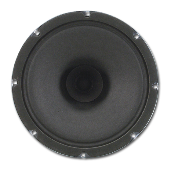
8" preassembled speaker package
Hide thumbs
Also See for SD72 Series:
- Specifications (2 pages) ,
- Specifications (2 pages) ,
- Installation instructions (1 page)
Table of Contents
Advertisement
Quick Links
SD72, SD72W, SD72WV
1. Use two wire nuts to attach the appropriate transformer wires to the field wiring.
2. Cut off the bare portion of the un-used leads and terminate with wire nuts.
Hardware Reference:
Model SD72 Mounts to all Atlas Sound 8" baffles except FA series
Models SD72W & SD72WV are compatible with the following Atlas Sound hardware items:
Mounting Rings:
76-8(E2), P77-8, P78-8
T-Bridges:
81-8R, 81-8S
Enclosures:
(EZ)95-8 Series, T95-8 Series, Q408, CS95-8, BMT95-8, BMT95-8-7
1601 JACK MCKAY BLVD.
ENNIS, TEXAS 75119 U.S.A.
TAP WATTAGE
70.7V
0.25
Red
0.5
White
1
Yellow
2
Blue
5
Brown
COMMON
BLACK
Frequency Response:
Sensitivity:
TAP WATTAGE
25V
0.25
Blue
0.5
Gray
1
White/wGreen
2
Violet
5
Orange
COMMON
BLACK
55Hz-8kHz
97dB
(1W/1M)
TELEPHONE: (800) 876-3333
FAX (800) 765-3435
1/1
AtlasSound.com
Advertisement
Table of Contents

Related Manuals for Atlas SD72 Series


Summary of Contents for Atlas SD72 Series
- Page 1 2. Cut off the bare portion of the un-used leads and terminate with wire nuts. Hardware Reference: Model SD72 Mounts to all Atlas Sound 8" baffles except FA series Models SD72W & SD72WV are compatible with the following Atlas Sound hardware items: Mounting Rings: 76-8(E2), P77-8, P78-8...
- Page 2 97dB and a dispersion angle of 105˚. Package includes factory installed 25V/70.7V line matching transformer with tap selections ranging from .25 to 5 Watts. It mounts a wide variety of Atlas Sound round and square baffles and enclosures to meet functional and aesthetic application requirements.
- Page 3 SD72 Polars (Normalized to Zero on Axis) (-6dB) SD72 Harmonic Distortion Frequency (Hz) 1601 JACK MCKAY BLVD. ENNIS, TEXAS 75119 U.S.A. AtlasSound.com TELEPHONE: (800) 876-3333 FAX (800) 765-3435...
- Page 4 SD72 Impedance Frequency (Hz) Octave Smoothing = 30.0% 1601 JACK MCKAY BLVD. ENNIS, TEXAS 75119 U.S.A. AtlasSound.com TELEPHONE: (800) 876-3333 FAX (800) 765-3435...
- Page 5 Attenuator Installations Wiring Each terminal will hold up to 2-16AWG stranded wire. For larger wires or home run situations, a small length of wire and a wire nut are recommended. Attach wire according to label on terminal block as shown to the right (Non-PA Models will not have the "VDC+" and "VDC-" terminals).
- Page 6 AA35G & AA60G Owner’s Manual Commercial Mixer Amplifier AA35G & AA60G Commercial Mixer Amplifier 1601 Jack McKay Blvd. • Ennis, Texas 75119 U.S.A. Telephone: 800.876.3333 • Fax: 800.765.3435 – 1 – AtlasIED.com Specifications are subject to change without notice.
-
Page 7: Table Of Contents
AA35G & AA60G Owner’s Manual Commercial Mixer Amplifier Table of Contents Important Safety Instructions ........................3 Introduction ............................5 Key Features ............................5 Applications ............................5 Front Panel Description ........................... 6 Rear Panel Description ..........................7 Installation ............................... 8 Rack Mounting ............................8 Input Wire and Connections ........................ -
Page 8: Important Safety Instructions
AA35G & AA60G Owner’s Manual Commercial Mixer Amplifier Important Safety Instructions The lightning flash with arrowhead symbol within an equilateral triangle, is intended to alert the user to the presence of uninsulated “dangerous voltage “ within the product’s enclosure that may be of sufficient magnitude to constitute a risk of electric shock to persons. - Page 9 AA35G & AA60G Owner’s Manual Commercial Mixer Amplifier WARNING - When The Device Is In Use • WARNING: For the terminals marked with symbol of may be of sufficient magnitude to constitute a risk of electric shock. The external wiring connected to the terminals requires installation by an instructed person or the used of ready-made leads or cords. •...
-
Page 10: Introduction
AA35G & AA60G Owner’s Manual Commercial Mixer Amplifier Introduction Congratulations and thank you for purchasing the AtlasIED AA35G/AA60G mixer amplifier. Small, compact, and engineered for reliability, the AtlasIED AA35G/AA60G will provide years of service and flexibility in background music and paging applications. Key Features •... -
Page 11: Front Panel Description
AA35G & AA60G Owner’s Manual Commercial Mixer Amplifier Front Panel 1. Input Signal Presence/Clip Indicators Green LED, one above each channel’s volume control, illuminates when input signal exceeds –40 dBu, and flashes brightly at threshold of audible distortion. 2. Master Level Control The Master Level control will raise or lower all the input channels together. -
Page 12: Rear Panel Description
AA35G & AA60G Owner’s Manual Commercial Mixer Amplifier Rear Panel 1. AC Power Inlet Detachable IEC accepts US or Euro style power cords. 2. Amplifier Outputs For loudspeaker connections, connect as follows or proceed to the setup section for typical wiring schemes. •... -
Page 13: Installation
AA35G & AA60G Owner’s Manual Commercial Mixer Amplifier 5. Line Output Connector 3-Pin Balanced Euroblock connector. Line level output is Pre Master Level control. Use this output to connect signal to a secondary amplifier. 6. Zone 2 Level Control Potentiometer adjusts level for both Zone 2 outputs. 7. -
Page 14: Input Wire And Connections
AA35G & AA60G Owner’s Manual Commercial Mixer Amplifier Choose Input Wire and Connectors AtlasIED recommends using balanced line (two-conductor plus shield), 22-24 gauge cables and connectors. Unbalanced line may also be used but may result in noise over long cable runs. The AA35G and AA60G have two types of input connectors: Euroblock and RCA. -
Page 15: Output Wire Connections
AA35G & AA60G Owner’s Manual Commercial Mixer Amplifier Choose Output Wire and Connectors Amplifier Output Connections: Slip the cable lugs under the output screw terminals and tighten (Figure 2.5). Slide the supplied non-touch cover over the output connections from top to bottom to cover them. AtlasIED recommends using high-quality, two-conductor, heavy gauge speaker wire and connectors. -
Page 16: Wiring The System
AA35G & AA60G Owner’s Manual Commercial Mixer Amplifier Wire the System Typical input and output wiring is shown in Figure 2.8. INPUTS: For Input 1, connect a microphone or balanced line-level signal to the Input 1 balanced input. Set the Mic/Line switch (DIP switch #1) accordingly. -
Page 17: Operation
AA35G & AA60G Owner’s Manual Commercial Mixer Amplifier Operation Powering Up 1. Turn Off any equipment connected to the Preamp Output connector. 2. Plug the amplifier’s power cord into a 3-wire grounded AC outlet. 3. Turn down the input volume controls. 4. -
Page 18: Troubleshooting
AA35G & AA60G Owner’s Manual Commercial Mixer Amplifier Troubleshooting CONDITION: No power to the mixer amplifier. POSSIBLE REASON: • The mixer amplifier’s power switch is Off. • The mixer amplifier is not plugged into the AC power receptacle. • The mixer amplifier’s high-voltage power supply circuit breaker has tripped. Verify that the AC mains voltage is correct. -
Page 19: Specifications
AA35G & AA60G Owner’s Manual Commercial Mixer Amplifier Specifications AA35G AA60G Electrical Specifications Power into 8 or 70V/100V Output (1kHz with 0.5% THD) Frequency Response (at 1 Watt from 8 Tap) 50Hz - 20kHz ±1 dB Technical Data Signal to Noise Ratio (Ref. to Rated Power, Master Volume at Minimum) Mic: >... - Page 20 AA35G & AA60G Owner’s Manual Commercial Mixer Amplifier Notes: 1601 Jack McKay Blvd. • Ennis, Texas 75119 U.S.A. Telephone: 800.876.3333 • Fax: 800.765.3435 – 15 – AtlasIED.com Specifications are subject to change without notice.
-
Page 21: Warranty
Visit our website at www.AtlasIED.com to see other Atlas products. ©2017 Atlas Sound L.P. The Atlas “Circle A” , Soundolier, and Atlas Sound are trademarks of Atlas Sound L.P. IED is a registered trademark of Innovative Electronic Designs LLC. All Rights Reserved. All other trademarks are the property of their respective owners. All specs are subject to change without notice. ATS005530 RevD 1/17 1601 Jack McKay Blvd.
Need help?
Do you have a question about the SD72 Series and is the answer not in the manual?
Questions and answers