
Related Manuals for GigaDevice Semiconductor GD32F310C-EVAL


Summary of Contents for GigaDevice Semiconductor GD32F310C-EVAL
- Page 1 GigaDevice Semiconductor Inc. GD32F310C-EVAL ® ® Cortex -M4 32-bit MCU User Guide Revision 1.0 (Mar. 2022)
-
Page 2: Table Of Contents
User Guide GD32F310C-EVAL Table of Contents TABLE OF CONTENTS ....................1 LIST OF FIGURES ......................3 LIST OF TABLES ......................4 1. SUMMARY ........................ 5 2. FUNCTION PIN ASSIGN ................... 5 3. GETTING STARTED ....................5 4. HARDWARE LAYOUT OVERVIEW ................6 4.1. - Page 3 User Guide GD32F310C-EVAL 5.6. USART_DMA ......................14 5.6.1. DEMO purpose ........................14 5.6.2. DEMO running result ......................14 5.7. ADC_conversion_triggered_by_timer ..............15 5.7.1. DEMO purpose ........................15 5.7.2. DEMO running result ......................15 5.8. I2C_EEPROM ......................15 5.8.1. DEMO purpose ........................15 5.8.2.
-
Page 4: List Of Figures
User Guide GD32F310C-EVAL List of Figures Figure 4-1. Schematic diagram of power supply ..................6 Figure 4-2. Schematic diagram of boot option ..................6 Figure 4-3. Schematic diagram of LED function ..................7 Figure 4-4. Schematic diagram of Key function ..................7 Figure 4-5. -
Page 5: List Of Tables
User Guide GD32F310C-EVAL List of Tables Table 2-1. Pin assignment ........................... 5 Table 4-1. Boot configuration ........................6 Table 6-1 Revision history ........................23 4/24... -
Page 6: Summary
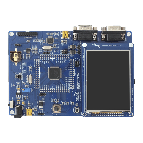
User Guide GD32F310C-EVAL Summary GD32F310C-EVAL uses GD32F310C8T6 as the main controller. As a evaluation board ® ® complete development platform of GD32F310 powered by Arm Cortex -M4 core, the board supports full range of peripherals. It uses mini-USB interface to supply 5V power. -
Page 7: Hardware Layout Overview
User Guide GD32F310C-EVAL power supply is OK. There are Keil version and IAR version of all projects. Keil version of the projects are created based on Keil MDK-ARM 4.74 uVision4. IAR version of the projects are created based on IAR Embedded Workbench for ARM 7.40.2. During use, the following points should be noted: 1. -
Page 8: Led
User Guide GD32F310C-EVAL 4.3. Figure 4-3. Schematic diagram of LED function 4.4. Figure 4-4. Schematic diagram of Key function 4.5. USART0 Figure 4-5. Schematic diagram of USART0 function USART To USB +3V3 VBUS 50V/0.01uF RS232_TX RS232_RX PA10 RTS# +3V3 CTS#... -
Page 9: Adc
User Guide GD32F310C-EVAL 4.6. Figure 4-6. Schematic diagram of ADC function 4.7. Figure 4-7 Schematic diagram of I2C function 4.8. QSPI-FLASH Figure 4-8. Schematic diagram of QSPI-FLASH function SPI Flash +3V3 +3V3 50V/0.1uF PB10 SPI1_IO2 10KΩ PB11 SPI1_IO3 SPIFlash_CS PB12... -
Page 10: Spi-Tft Lcd
User Guide GD32F310C-EVAL 4.9. SPI-TFT LCD Figure 4-9. Schematic diagram of SPI-TFT LCD function 4.10. IFRP Figure 4-10. Schematic diagram of IFRP function +3V3 100Ω LED5 IR333C-A TIMER_CH0 +3V3 100Ω IR_OUT IRM-3638T 8050 10V/4.7uF 1KΩ 10KΩ 9/24... -
Page 11: Gd-Link
User Guide GD32F310C-EVAL 4.11. GD-Link Figure 4-11. Schematic diagram of GD-Link function MCU SWD PA0-WKUP +3V3 JP100 PB2/BOOT1 PB3/JTDO L_SWDIO L_TMS/IO PB4/JNTRST L_SWDCK L_TCK/CLK L_TDO/SWO L_TDI 4× 1P2.54 L_USB_Ctr L_TReset L_LED1 LED0603 PA10 PB10 L_USB_DM PA11 PB11 L_USB_DP L_LED1 R109 470Ω... -
Page 12: Mcu
Learn to use GPIO for controlling the LED. Learn to use SysTick to generate 1ms delay. GD32F310C-EVAL board has four LEDs. The LED1, LED2, LED3 and LED4 are controlled by GPIO. This demo will show how to light the LEDs. 5.1.2. -
Page 13: Gpio_Key_Polling_Mode
Learn to use SysTick to generate 1ms delay. GD32F310C-EVAL board has three keys and four LEDs. The three keys are Reset key, Tamper key and Wakeup key. The LED1, LED2, LED3 and LED4 are controlled by GPIO. This demo will show how to use the Tamper key to control the LED2. When press down the Tamper Key, it will check the input value of the IO port. -
Page 14: Usart_Printf
User Guide GD32F310C-EVAL 5.4. USART_Printf 5.4.1. DEMO purpose This Demo includes the following functions of GD32 MCU: Learn to retarget the C library printf function to the USART 5.4.2. DEMO running result Download the program <04_USART_Printf> to the EVAL board and run. -
Page 15: Usart_Dma
User Guide GD32F310C-EVAL 5.6. USART_DMA 5.6.1. DEMO purpose This Demo includes the following functions of GD32 MCU: Learn to use the COM transmit and receive using DMA 5.6.2. DEMO running result Download the program <06_USART_DMA> to the EVAL board and run. And connect the serial line to COM of EVAL board. -
Page 16: Adc_Conversion_Triggered_By_Timer
<07_ADC_conversion_triggered_by_timer> GD32F310C-EVAL board, adjust the adjustable potentiometer knob to change the analog input. The ADC, which is triggered by TIMER0 CH0 event, will convert the analog input, and you will see the result, a voltage curve, on the LCD. The curve adjusts with the analog input. -
Page 17: Qspi_Flash
User Guide GD32F310C-EVAL The output information via the serial port is as following. 5.9. QSPI_FLASH 5.9.1. DEMO purpose This demo includes the following functions of GD32 MCU: Learn to use the Quad-SPI mode of SPI unit to read and write NOR Flash with the SPI interface 5.9.2. -
Page 18: Spi_Tft_Lcd_Driver
Learn how to use SPI to drive TFT LCD screen and display GD32F310C-EVAL board has a TFT LCD screen which supports SPI interface. In this demo, tests of font, number, draw and color are displayed on the LCD screen respectively. -
Page 19: Rcu_Clock_Out
User Guide GD32F310C-EVAL turned on and then turned off for test. After that, the LCD screen on the board will display the GUI tests in infinite loop. 5.11. RCU_Clock_Out 5.11.1. DEMO purpose This Demo includes the following functions of GD32 MCU: ... -
Page 20: Ctc_Calibration
User Guide GD32F310C-EVAL 5.12. CTC_Calibration 5.12.1. DEMO purpose This demo includes the following functions of GD32 MCU: Learn to use external low speed crystal oscillator (LXTAL) to implement the CTC calibration function Learn to use clock trim controller (CTC) to trim internal 48MHz RC oscillator (IRC48M) -
Page 21: Demo Running Result
User Guide GD32F310C-EVAL 5.14.2. DEMO running result Download the program <14_RTC_Calendar> to the EVAL board and run. If the development board run the program for the first time, serial port output following information "Configure RTC time" It requires the user to set up hours、minutes and seconds. -
Page 22: Irinfrared_Transceiver
This Demo includes the following functions of GD32 MCU: Learn to use TIMER output PWM wave Learn to update channel value 5.16.2. DEMO running result Download the program <16_TIMER_Breath_LED> to the GD32F310C-EVAL board and run. PA8 should not be reused by other peripherals. 21/24... - Page 23 User Guide GD32F310C-EVAL When the program is running, you can see LED1 lighting from dark to bright gradually and then gradually darken, ad infinitum, just like breathing as rhythm. 22/24...
-
Page 24: Revision History
User Guide GD32F310C-EVAL Revision history Table 6-1 Revision history Revision No. Description Date Initial Release Mar.06, 2022 23/24... - Page 25 Important Notice This document is the property of GigaDevice Semiconductor Inc. and its subsidiaries (the "Company"). This document, including any product of the Company described in this document (the “Product”), is owned by the Company under the intellectual property laws and treaties of the People’s Republic of China and other jurisdictions worldwide.
Need help?
Do you have a question about the GD32F310C-EVAL and is the answer not in the manual?
Questions and answers