Table of Contents
Advertisement
Quick Links
Advertisement
Table of Contents

Related Manuals for GigaDevice Semiconductor GD32350G-START


Summary of Contents for GigaDevice Semiconductor GD32350G-START
- Page 1 GigaDevice Semiconductor Inc. GD32350G-START User Guide V2.0...
-
Page 2: Table Of Contents
User Guide GD32350G-START Table of Contents Table of Contents ......................1 List of Figures ........................ 2 List of Tables ........................3 1. Summary ........................4 2. Function Pin Assign ....................4 3. Getting started ......................4 4. Hardware layout overview ..................5 4.1. -
Page 3: List Of Figures
User Guide GD32350G-START List of Figures Figure 4-1 Schematic diagram of power supply ....................5 Figure 4-2 Schematic diagram of boot option....................5 Figure 4-3 Schematic diagram of LED function ....................5 Figure 4-4 Schematic diagram of Key function ....................6 Figure 4-5 Schematic diagram of USBFS function ................... -
Page 4: List Of Tables
User Guide GD32350G-START List of Tables Table 2-1 Pin assignment ............................4 Table 4-1 Boot configuration ..........................5 Table 6-1 Revision history ............................. 12 3 /13... -
Page 5: Summary
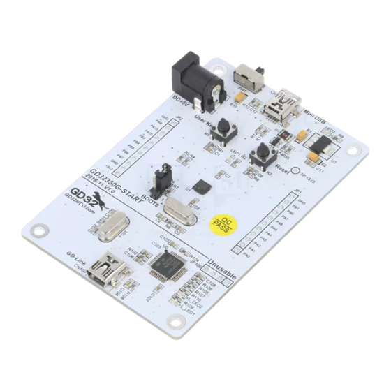
User Guide GD32350G-START Summary GD32350G-START board uses GD32F350G8 as the main controller. As a complete development platform of GD32F3x0 powered by ARM® Cortex™-M4 core, the board supports full range of peripherals. It uses mini-USB interface or AC/DC adapter to supply 5V power. -
Page 6: Hardware Layout Overview
User Guide GD32350G-START C/C++ in Option for Target. 3. If you use IAR to open the project, install IAR_GD32F3x0_ADDON.2.0.0.exe to load the associated files. Hardware layout overview 4.1. Power supply Figure 4-1 Schematic diagram of power supply DC-10B +U5V LM1117-3.3... -
Page 7: Key
User Guide GD32350G-START 4.4. Figure 4-4 Schematic diagram of Key function 4.5. USBFS Figure 4-5 Schematic diagram of USBFS function 47KΩ S8550 470R +U5V 16V/10uF,AVX USB_VBUS VBUS PA11 USB_DM 22Ω PA12 USB_DP 22Ω Shield Mini_USB 1MΩ 50V/4700pF 6 /13... -
Page 8: Gd-Link
User Guide GD32350G-START 4.6. GD-Link Figure 4-6 Schematic diagram of GD-Link function MCU SWD PA0-WKUP PB2/BOOT1 +3V3 JP100 PB3/JTDO L_TMS/IO PB4/JNTRST L_SWDIO L_TCK/CLK L_SWDCK L_TDO/SWO L_TDI 4× 1P2.54 L_USB_Ctr L_TReset L_LED1 LED0603 PA10 PB10 L_USB_DM PA11 PB11 L_USB_DP L_LED1 R109 1KΩ... -
Page 9: Mcu
Learn to use GPIO for controlling the LED Learn to use SysTick to generate 1ms delay GD32350G-START board has one LED. The LED1 is controlled by GPIO. This demo will show how to light the LED. 5.1.2. DEMO running Result Download the program <01_GPIO_Running_Led>... -
Page 10: Demo Running Result
Learn to use SysTick to generate 1ms delay GD32350G-START board has two keys and one LED. The two keys are Reset key and User key. The LED1 is controlled by GPIO. This demo will show how to use the User key to control the LED1. When press down the User Key, it will check the input value of the IO port. -
Page 11: Usbh_Msc_Host
User Guide GD32350G-START Learn how to use the USBFS peripheral Learn how to implement USB CDC device Start board has one USBFS interface. In this demo, the Start board is enumerated as an USB virtual COM port, which would be shown in device manager of PC as below. This demo makes the USB device looks like a serial port, and loops back the contents of a text file over USB port. - Page 12 User Guide GD32350G-START DEMO running Result Insert the OTG cable to the USB port, download the program <04_USBFS\Host\MSC> to the Start board and run. If an Udisk has been attached, firstly, press the user key, then this demo will write file to the Udisk.
-
Page 13: Revision History
User Guide GD32350G-START Revision history Table 6-1 Revision history Revision No. Description Date Initial Release Jun.28, 2017 Updated format across the whole document Jun.1, 2019 12 /13... - Page 14 Important Notice This document is the property of GigaDevice Semiconductor Inc. and its subsidiaries (the "Company"). This document, including any product of the Company described in this document (the “Product”), is owned by the Company under the intellectual property laws and treaties of the People’s Republic of China and other jurisdictions worldwide.
Need help?
Do you have a question about the GD32350G-START and is the answer not in the manual?
Questions and answers