
Subscribe to Our Youtube Channel
Related Manuals for TLV JH3LH-X


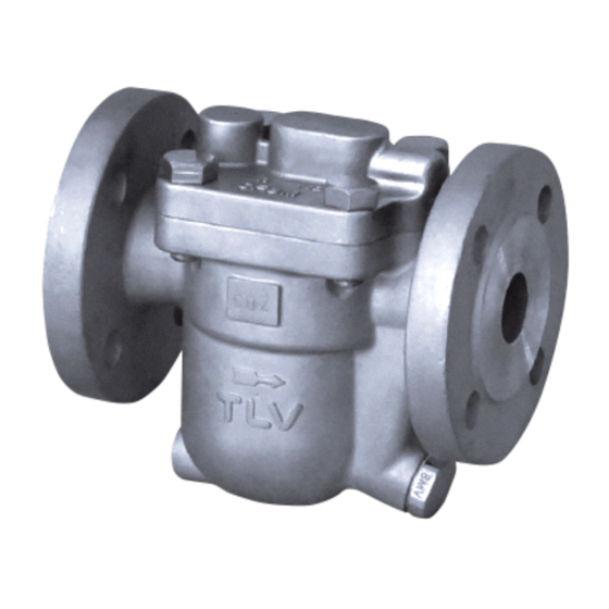
Summary of Contents for TLV JH3LH-X
- Page 1 Instruction Manual Free Float Steam Trap with X-element Model: JH3LH-X 172-65775M-00 Publication date 18 April 2023 Copyright © 2023 TLV CO., LTD.
-
Page 2: Table Of Contents
Operation ..........................7 Specifications ........................... 9 Configuration .......................... 10 Installation ..........................11 Maintenance ........................... 12 Disassembly/Reassembly ...................... 14 Instructions for Plug/Holder Disassembly and Reassembly ........... 18 Troubleshooting ........................19 TLV EXPRESS LIMITED WARRANTY ................... 20 Service ........................... 22 Options ........................... 23... -
Page 3: Introduction
Introduction Thank you for purchasing the TLV free float steam trap. This product has been thoroughly inspected before being shipped from the factory. When the product is delivered, before doing anything else, check the specifications and external appearance to make sure nothing is out of the ordinary. Also be sure to read this manual carefully before use and follow the instructions to be sure of using the product properly. -
Page 4: Safety Considerations
• The three types of cautionary items above are very important for safety: be sure to observe all of them as they relate to installation, use, maintenance and repair. Furthermore, TLV accepts no responsibility for any accidents or damage occurring as a result of failure to observe these precautions. - Page 5 Caution Be sure to use only the recommended components when repairing the product, and NEVER attempt to modify the product in any way. Failure to observe these precautions may result in damage to the product and burns or other injury due to malfunction or the discharge of fluids. Caution Use only under conditions in which no freeze-up will occur.
-
Page 6: Checking The Piping
4. Have isolation valves been installed at the inlet and outlet? If the outlet is subject to back pressure, has a check valve (TLV-CK) been installed? 5. Is the inlet pipe as short as possible, with as few bends as possible, and installed so the liquid will flow naturally down into the product? 6. -
Page 7: Operation
Operation Principles of air and condensate discharge: 1. Initial Air and Cold Condensate Discharge At startup, before steam is supplied, the trap is cold so the X-element is contracted and the air vent valve seat (A) is open. This allows for the rapid discharge of air through the air vent valve (A) and cold condensate through the orifice (B), when steam is first supplied to the system. - Page 8 4. Closed Position When the condensate flow rate decreases, the float falls as condensate is discharged, closing off the orifice (B). A water seal is maintained at all times over the orifice (B) to prevent steam loss. Note The high steam temperature causes the X-element to expand, keeping the air vent closed. Steam Condensate...
-
Page 9: Specifications
Specifications Caution Install properly and DO NOT use this product outside the recommended operating pressure, temperature and other specification ranges. Improper use may result in such hazards as damage to the product or malfunctions that may lead to serious accidents. Local regulations may restrict the use of this product to below the conditions quoted. -
Page 10: Configuration
Configuration Part Name Part Name Body Nameplate ✓ Cover Float Cover ✓ ✓ Float X-element Guide ✓ Orifice Plug X-element ✓ ✓ ✓ Orifice Plug Gasket Spring Clip ✓ ✓ Orifice Air Vent Valve Seat ✓ ✓ Orifice Gasket Connector ✓... -
Page 11: Installation
6. Open the inlet and outlet valves and ensure that the product functions properly. If there is a problem, determine the cause using the "Troubleshooting" section in this manual. Tolerance Angle for Installation: 5° Make sure the product is installed with the raised TLV lettering on the body horizontal. -
Page 12: Maintenance
(When conducting a visual inspection, flash steam is sometimes mistaken for steam leakage. For this reason, the use of a steam trap diagnostic instrument such as TLV TrapMan in conjunction with the visual inspection is highly recommended.) - Page 13 Parts Inspection When parts have been removed, or during periodic inspections, use the following table to inspect the parts and replace any that are found to be defective. Gaskets: Check for warping or scratches Screen: Check for clogging or corrosion X-element: Check for scratches Air Vent Valve Seat: Check for scratches Float: Check for scratches or dents...
-
Page 14: Disassembly/Reassembly
Disassembly/Reassembly Warning NEVER apply direct heat to the float. The float may explode due to increased internal pressure, causing accidents leading to serious injury or damage to property and equipment. Caution When disassembling or removing the product, wait until the internal pressure equals atmospheric pressure and the surface of the product has cooled to room temperature. - Page 15 Disassembly/Reassembly of Components Inside the Cover Part Name & No. During Disassembly During Reassembly Spring Clip 14 Pinch the insides together and remove Insert securely into the groove in the from the X-element guide guide X-element 13 Remove from the X-element guide Insert after making sure of the correct orientation Air Vent Valve...
- Page 16 Table of Tightening Torques Torque Distance Across Flats Part Name & No. N·m Cover Bolt 17 Air Vent Valve Seat 15 Orifice Plug 4 Orifice 6 Note • Coat all threaded portions with anti-seize. • If drawings or other special documentation were supplied for the product, any torque given there takes precedence over values shown here.
- Page 17 Exploded View Part Name Part Name Body Nameplate Cover Float Cover Float X-element Guide Orifice Plug X-element Orifice Plug Gasket Spring Clip Orifice Air Vent Valve Seat Orifice Gasket Connector Screen Cover Bolt Cover Gasket...
-
Page 18: Instructions For Plug/Holder Disassembly And Reassembly
Instructions for Plug/Holder Disassembly and Reassembly The seal on the threaded plugs/holders found on TLV products is formed by a flat metal gasket. There are various installation orientations for the gaskets, such as horizontal, diagonal and downward, and the gasket may be pinched in the thread recesses during assembly. -
Page 19: Troubleshooting
Troubleshooting Warning NEVER apply direct heat to the float. The float may explode due to increased internal pressure, causing accidents leading to serious injury or damage to property and equipment. Caution When disassembling or removing the product, wait until the internal pressure equals atmospheric pressure and the surface of the product has cooled to room temperature. -
Page 20: Tlv Express Limited Warranty
TLV; or 4. disasters or forces of nature or Acts of God; or 5. abuse, abnormal use, accidents or any other cause beyond the control of TLV, TII or TLV group companies; or 6. improper storage, maintenance or repair; or 7. - Page 21 HEREBY, INCLUDING THE IMPLIED WARRANTIES OF MERCHANTABILITY AND FITNESS FOR A PARTICULAR PURPOSE, DO NOT COVER, AND NEITHER TLV, TII NOR ITS TLV GROUP COMPANIES WILL IN ANY EVENT BE LIABLE FOR, INCIDENTAL OR CONSEQUENTIAL DAMAGES, INCLUDING, BUT NOT LIMITED TO LOST PROFITS, THE COST OF DISASSEMBLY AND SHIPMENT OF THE DEFECTIVE PRODUCT, INJURY TO OTHER PROPERTY, DAMAGE TO BUYER’S OR THE FIRST...
-
Page 22: Service
Service For Service or Technical Assistance: Contact your TLV representative or your regional TLV office. In Europe: Tel: [49]-(0)7263-9150-0 Fax: [49]-(0)7263-9150-50 Daimler-Benz-Straße 16-18, 74915 Waibstadt, Germany Tel: [44]-(0)1242-227223 Fax: [44]-(0)1242-223077 Units 7 & 8, Furlong Business Park, Bishops Cleeve, Gloucestershire GL52 8TW, U.K. -
Page 23: Options
Options The options shown below are available for this product on request. Please compare with the product you received. Options for Area A (Standard: Without drain plug) With Drain Plug Torque Distance Across Flats N·m...
Need help?
Do you have a question about the JH3LH-X and is the answer not in the manual?
Questions and answers