Table of Contents

Related Manuals for TLV J10


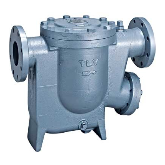
Summary of Contents for TLV J10
- Page 1 ISO 9001 ISO14001 Manufacturer Kakogawa, Japan is approved by LRQA Ltd. to ISO 9001/14001 Instruction Manual Float Dynamic Steam Trap Featured Model: J10 172-65237M-04 Publication date 19 February 2024 Copyright © 2024 TLV CO., LTD.
-
Page 2: Table Of Contents
Checking the Piping ........................6 Specifications ........................... 7 Operation ..........................8 Configuration .......................... 10 Installation ..........................11 Lock Release Valve Operation ....................13 Maintenance ........................... 14 Disassembly/Reassembly ...................... 16 Troubleshooting ........................20 TLV EXPRESS LIMITED WARRANTY ................... 21 Service ........................... 23... -
Page 3: Introduction
Introduction Thank you for purchasing the TLV float dynamic steam trap. This product has been thoroughly inspected before being shipped from the factory. When the product is delivered, before doing anything else, check the specifications and external appearance to make sure nothing is out of the ordinary. Also be sure to read this manual carefully before use and follow the instructions to be sure of using the product properly. -
Page 4: Safety Considerations
• The three types of cautionary items above are very important for safety: be sure to observe all of them as they relate to installation, use, maintenance and repair. Furthermore, TLV accepts no responsibility for any accidents or damage occurring as a result of failure to observe these precautions. - Page 5 Caution Be sure to use only the recommended components when repairing the product, and NEVER attempt to modify the product in any way. Failure to observe these precautions may result in damage to the product and burns or other injury due to malfunction or the discharge of fluids. Caution Use only under conditions in which no freeze-up will occur.
-
Page 6: Checking The Piping
Checking the Piping Caution Use only under conditions in which no water hammer will occur. The impact of water hammer may damage the product, leading to fluid discharge, which may cause burns or other injury. Check to make sure that the pipes to be connected to the product have been installed properly. -
Page 7: Specifications
Specifications Caution Install properly and DO NOT use this product outside the recommended operating pressure, temperature and other specification ranges. Improper use may result in such hazards as damage to the product or malfunctions that may lead to serious accidents. Local regulations may restrict the use of this product to below the conditions quoted. -
Page 8: Operation
Operation Principles of air and condensate discharge: Valve opening & initial condensate discharge At start-up, when a large quantity of condensate flows into the trap, the float (A) rises by buoyancy, opening the pilot orifice (E). Condensate flows through the pilot orifice (E) into the control chamber (F), increasing the pressure there. - Page 9 Float dynamic principle When a large quantity of condensate flows into the trap, the float (A) rises immediately, opening the pilot orifice (E) wide. Condensate passes through the pilot orifice at a high velocity into the control chamber (F), where the pressure increases rapidly due to flashing condensate. The rapid expansion causes a force to be exerted on the main valve (B), opening the large orifice on the main valve seat (C) instantly.
-
Page 10: Configuration
Turn Stopper Cover Gasket Snap Ring Spring Washer Spring Washer Main Valve Seat Bolt Turn Stopper Bolt Valve Cover Bolt Float Cover O-ring Float Cover Retainer Float Drain Plug Gasket Valve Cover Gasket Plug Gasket Cover Bolt For Steel Body J10... -
Page 11: Installation
Secure sufficient space for inspection and maintenance. If there is a problem, determine the cause using the “Troubleshooting” section in this manual. Tolerance Angle for Installation: 5° 5° 5° Make sure the product is installed with the raised TLV lettering on the body horizontal. - Page 12 For Start-up Operation Just after the product is installed or when it has been idle for a long period of time, be sure to blow out the rust and scale from the inside of the piping before opening the trap inlet valve.
-
Page 13: Lock Release Valve Operation
Lock Release Valve Operation Caution Be sure to use only the recommended components when repairing the product, and NEVER attempt to modify the product in any way. Failure to observe these precautions may result in damage to the product and burns or other injury due to malfunction or the discharge of fluids. Do not leave the lock release valve open during regular operation. -
Page 14: Maintenance
Periodically (at least biannually) the operation should also be checked by using diagnostic equipment, such as a stethoscope, thermometer, TLV Pocket TrapMan or TLV TrapMan. A complete disassembly and inspection should be performed at least once every 3 years. - Page 15 Parts Inspection When parts have been removed, or during periodic inspections, use the following table to inspect the parts and replace any that are found to be defective. Gaskets, O-rings: Check for warping or damage Sleeve: Check for wear Main Valve Seat (shaft): Check for dirt, oil film, wear or damage Main Valve, Main Valve Seat: Check for build-up or wear on seating surfaces Piston Ring Set: Check for wear, warping or damage Float: Check for deformation, scratches or dents...
-
Page 16: Disassembly/Reassembly
Disassembly/Reassembly Warning NEVER apply direct heat to the float. The float may explode due to increased internal pressure, causing accidents leading to serious injury or damage to property and equipment. Caution Use hoisting equipment for heavy objects (weighing approximately 20 kg (44 lb) or more). Failure to do so may result in back strain or other injury if the object should fall. - Page 17 Disassembly/Reassembly of the Main Valve Unit and its Components Part Name & No. During Disassembly During Reassembly Valve Cover Bolt Remove with a socket wrench Coat threads with anti-seize; tighten evenly, being careful not to tighten one side more than the other; tighten to the proper torque Valve Cover 9 Remove the cover...
- Page 18 Disassembly/Reassembly of the Lock Release Valve Part Name & No. During Disassembly During Reassembly Lock Release Remove with a socket wrench Coat threads with anti-seize; consult Valve Cap 28 the table of tightening torques and tighten to the proper torque Packing Holder Remove with a socket wrench Coat threads with anti-seize;...
- Page 19 Table of Tightening Torques Torque Distance Across Flats Part Name & No. N·m Valve Cover Bolt 16 Cover Bolt 20 Packing Holder Nut 27 Lock Release Valve Cap 28 Lock Release Valve Body 24 Lock Release Valve Seat 21 U-Nut 8 Main Valve Seat Bolt 15 Turn Stopper Bolt 35 Drain Plug 30 (Iron Body)
-
Page 20: Troubleshooting
Troubleshooting Warning NEVER apply direct heat to the float. The float may explode due to increased internal pressure, causing accidents leading to serious injury or damage to property and equipment. Caution When disassembling or removing the product, wait until the internal pressure equals atmospheric pressure and the surface of the product has cooled to room temperature. -
Page 21: Tlv Express Limited Warranty
Subject to the limitations set forth below, TLV CO., LTD., a Japanese corporation ("TLV"), warrants that products which are sold by it, TLV International Inc. ("TII") or one of its group companies excluding TLV Corporation (a corporation of the United States of America), (hereinafter the "Products") are designed and manufactured by TLV, conform to the... - Page 22 HEREBY, INCLUDING THE IMPLIED WARRANTIES OF MERCHANTABILITY AND FITNESS FOR A PARTICULAR PURPOSE, DO NOT COVER, AND NEITHER TLV, TII NOR ITS TLV GROUP COMPANIES WILL IN ANY EVENT BE LIABLE FOR, INCIDENTAL OR CONSEQUENTIAL DAMAGES, INCLUDING, BUT NOT LIMITED TO LOST PROFITS, THE COST OF DISASSEMBLY AND SHIPMENT OF THE DEFECTIVE PRODUCT, INJURY TO OTHER PROPERTY, DAMAGE TO BUYER’S OR THE FIRST...
-
Page 23: Service
Service For Service or Technical Assistance: Contact your TLV representative or your regional TLV office. In Europe: Tel: [49]-(0)7263-9150-0 Daimler-Benz-Straße 16-18, 74915 Waibstadt, Germany Tel: [44]-(0)1242-227223 Units 7 & 8, Furlong Business Park, Bishops Cleeve, Gloucestershire GL52 8TW, U.K. Tel:...
Need help?
Do you have a question about the J10 and is the answer not in the manual?
Questions and answers