
Related Manuals for TLV QuickTrap FJ32D-B


Summary of Contents for TLV QuickTrap FJ32D-B
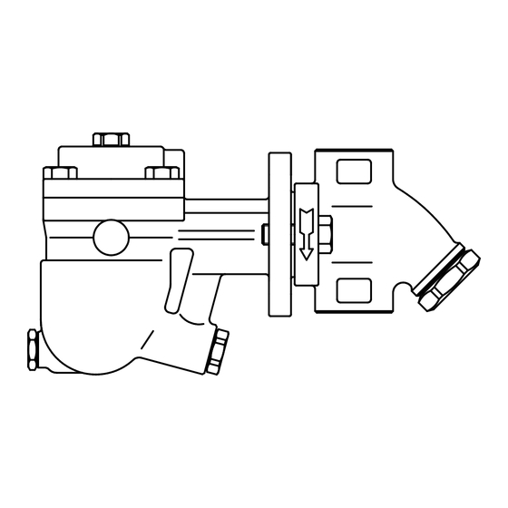
- Page 1 172-65419MA-05 (FJ32D-B +BD2) 1 October 2021 Free Float Steam Trap with Bimetal FJ32D-B QuickTrap ® J32D-B Trap Unit Copyright © 2021 by TLV CO., LTD. All rights reserved...
-
Page 2: Table Of Contents
If detailed instructions for special order specifications or options not contained in this manual are required, please contact TLV for full details. This instruction manual is intended for use with the model(s) listed on the front cover. -
Page 3: Safety Considerations
The three types of cautionary items above are very important for safety: be sure to observe all of them as they relate to installation, use, maintenance and repair. Furthermore, TLV accepts no responsibility for any accidents or damage occurring as a result of failure to observe these precautions Symbols Indicates a DANGER, WARNING or CAUTION item. - Page 4 When disassembling or removing the product, wait until the CAUTION internal pressure equals atmospheric pressure and the surface of the product has cooled to room temperature. Disassembling or removing the product when it is hot or under pressure may lead to discharge of fluids, causing burns, other injuries or damage.
-
Page 5: Checking The Piping
4. Have isolation valves been installed at the inlet and outlet? If the outlet is subject to back pressure, has a check valve (TLV-CK) been installed? 5. Is the inlet pipe as short as possible, with as few bends as possible, and installed so the liquid will flow naturally down into the product? 6. -
Page 6: Operation
Operation Principles of air and condensate discharge: 1. Air and Cold Condensate Discharge at Startup At startup, before steam is supplied, the system is cold and the bimetal plate is flexed downward, keeping the air vent valve (A) open. This allows for the rapid discharge of air through vent (A) and cold condensate through orifice (B) when steam is first supplied to the system. -
Page 7: Specifications
***The nominal diameter is not printed on the trap unit nameplate when the trap unit is shipped by itself. Compatibility The FJ32 QuickTrap series employ a unique TLV connector unit (F46J) and are not compatible with QuickTraps using connector unit F32 or others. Trap and connector units must only be used with compatible models. -
Page 8: Configuration
Configuration Name C M R F No. Name C M R Body Bimetal Plate Cover Air Vent Case Float Cover Bolt Orifice Connector Orifice Gasket Inner Connector Gasket ... -
Page 9: Installation
Installation Install properly and DO NOT use this product outside the recommended operating pressure, temperature and other specification ranges. CAUTION Improper use may result in such hazards as damage to the product or malfunctions which may lead to serious accidents. Local regulations may restrict the use of this product to below the conditions quoted. - Page 10 Installation Examples: Horizontal Piping Incorrect Nameplate is not facing Connector Flange is not in the Correct upwards vertical plane Nameplate Connector Flange Ground Ground Ground Ground Ground Installation Examples: Vertical Piping Incorrect Correct Nameplate is not facing upwards. Connector Nameplate Flange Ground Ground...
-
Page 11: Maintenance
(When conducting a visual inspection, flash steam is sometimes mistaken for steam leakage. For this reason, the use of a steam trap diagnostic instrument - such as TLV TrapMan - in conjunction with the visual inspection is highly recommended.) -
Page 12: Disassembly/Reassembly
Disassembly/Reassembly NEVER apply direct heat to the float. The float may explode due to increased internal pressure, causing accidents leading to serious injury WARNING or damage to property and equipment. When disassembling or removing the product, wait until the internal pressure equals atmospheric pressure and the surface of the product CAUTION has cooled to room temperature. -
Page 13: Orifice Plug
Disassembly/Reassembly of Components Inside the Cover Figure B Part During Disassembly During Reassembly Snap Ring Pinch the insides together and Insert it securely into the remove from the cover groove Screen Remove, being careful not to Replace, being careful not to misshape misshape Bimetal/... - Page 14 Table of Tightening Torques Torque Distance Across Flats Part Name Nm (lbf·ft) (in) Orifice (22) Orifice Plug (59) Air Vent Valve Seat (22) Cover Bolt (37) Screen Holder (110) Bolt (Trap Unit / Connector Unit) (59) Cover Plug (22) (1 Nm 10 kgcm) NOTE: -Coat all threaded portions with anti-seize.
-
Page 15: Air Vent Valve Seat
Exploded View Cover Bolt Plug Plug Gasket Cover Connector Cover Gasket Bimetal Screen Case (Float Cover) Air Vent Valve Seat Air Vent Float Valve Plug Bimetal Plate Trap Body Screen Snap Ring Inner Connector Gasket Outer Connector Gasket Connector Body Connector Bolt Orifice Gasket... -
Page 16: Instructions For Plug/Holder Disassembly And Reassembly
Instructions for Plug/Holder Disassembly and Reassembly The seal on the threaded plugs/holders found on TLV products is formed by a flat metal gasket. There are various installation orientations for the gaskets, such as horizontal, diagonal and downward, and the gasket may be pinched in the thread recesses during assembly. -
Page 17: Troubleshooting
Troubleshooting When disassembling or removing the product, wait until the internal pressure equals atmospheric pressure and the surface of the product CAUTION has cooled to room temperature. Disassembling or removing the product when it is hot or under pressure may lead to discharge of fluids, causing burns, other injuries or damage. -
Page 18: Tlv Express Limited Warranty
Subject to the limitations set forth below, TLV CO., LTD., a Japanese corporation (“TLV”), warrants that products which are sold by it, TLV International Inc. (“TII”) or one of its group companies excluding TLV Corporation (a corporation of the United States of America), (hereinafter the “Products”) are designed and manufactured by TLV, conform to the... - Page 19 WARRANTY NOT NEGATED HEREBY, AND ANY IMPLIED WARRANTY NOT NEGATED HEREBY, INCLUDING THE IMPLIED WARRANTIES OF MERCHANTABILITY AND FITNESS FOR A PARTICULAR PURPOSE, DO NOT COVER, AND NEITHER TLV, TII NOR ITS TLV GROUP COMPANIES WILL IN ANY EVENT BE LIABLE FOR, INCIDENTAL OR...
-
Page 20: Service
Service For Service or Technical Assistance: Contact your TLV representative or your regional TLV office. In Europe: Tel: [49]-(0)7263-9150-0 Daimler-Benz-Straße 16-18, 74915 Waibstadt, Germany Fax: [49]-(0)7263-9150-50 Tel: [44]-(0)1242-227223 Units 7 & 8, Furlong Business Park, Bishops Cleeve, Gloucestershire GL52 8TW, U.K. -
Page 21: Options
(26) (1 Nm 10 kgcm) Options for Area B (screen holder) With Blowdown Valve (TLV-BD2) Always wear eye protection and heat-resistant gloves when operating CAUTION the blowdown valve. Failure to do so may result in burns or other injury. - Page 22 BD2 Blowdown Valve Operation The BD2 valve is in the closed position when the BD2 is shipped from the factory. Before attempting to operate the BD2, reconfirm that the BD2 valve is still in the closed position. Locate the blow outlet and, during operation, stand to the side and well clear of it, as the jet of condensate or steam could cause burns.
Need help?
Do you have a question about the QuickTrap FJ32D-B and is the answer not in the manual?
Questions and answers