Table of Contents
Advertisement
Installer's Guide
TRANE Link Variable Speed Heat Pumps and Air
Conditioners
4TWV7X24A1000A
4TWV7X36A1000A
4TWV7X48A1000A
4TWV7X60A1000A
The Diagnostics Mobile App is available by scanning a QR
code located inside this unit or by searching for the Trane or
American Standard Diagnostics App in your App Store ® .
This system must include a A/T HUI2360A200U thermostat
and a TSYS2C60A2VVU system controller to operate and is
Link communicating only.
Only qualified personnel should install and service the equipment. The installation, starting up, and servicing of heating, ventilating, and air-conditioning
equipment can be hazardous and requires specific knowledge and training. Improperly installed, adjusted or altered equipment by an unqualified person
could result in death or serious injury. When working on the equipment, observe all precautions in the literature and on the tags, stickers, and labels that
are attached to the equipment.
April 2023
4TTV7X24A1000A
4TTV7X36A1000A
4TTV7X48A1000A
4TTV7X60A1000A
S S A A F F E E T T Y Y W W A A R R N N I I N N G G
1 1 8 8 - - B B C C 1 1 1 1 1 1 D D 1 1 - - 1 1 A A - - E E N N
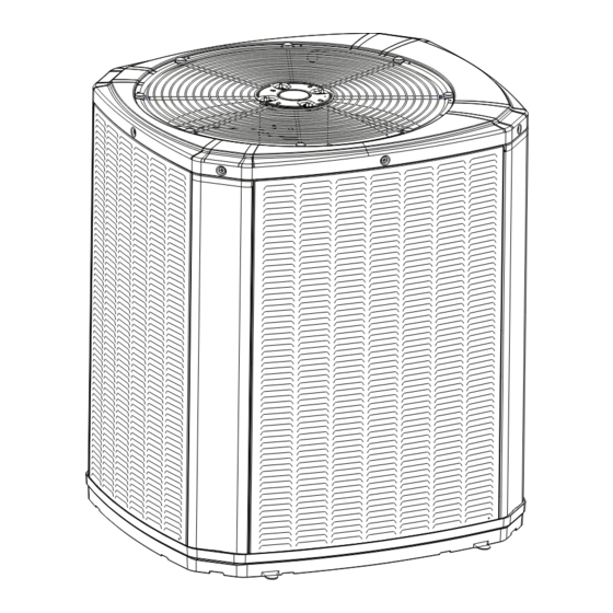
N N o o t t e e : : "Graphics in this document are for representation
only. Actual model may differ in appearance."
Advertisement
Table of Contents

Related Manuals for Trane 4TWV7X24A1000A


Summary of Contents for Trane 4TWV7X24A1000A
- Page 1 Actual model may differ in appearance.” The Diagnostics Mobile App is available by scanning a QR code located inside this unit or by searching for the Trane or American Standard Diagnostics App in your App Store ® . This system must include a A/T HUI2360A200U thermostat and a TSYS2C60A2VVU system controller to operate and is Link communicating only.
- Page 2 E E a a r r t t h h c c o o n n n n e e c c t t i i o o n n e e s s s s e e n n t t i i a a l l b b e e f f o o r r e e c c o o n n n n e e c c t t i i n n g g e e l l e e c c t t r r i i c c a a l l s s u u p p p p l l y y . . 18-BC111D1-1A-EN ©2023 Trane...
- Page 3 • S8V2xxxxxxVC remote disconnects before servicing. Note: See AHRI directory for approved indoor and outdoor model combinations. Only Trane / American Standard coils and air handlers are approved for use with variable speed outdoor unit. Table 1. Operating Range Cooling 45°...
-
Page 4: Table Of Contents
Table of Contents Unit Location Considerations ....5 Integrated Variable Speed Control Board LED Indicators ......19 Suggested Locations. -
Page 5: Unit Location Considerations
Unit Location Considerations Table 2. Unit Dimensions and Weight H x D x W (in) Weight * (lb) Models 4TWV7X24A 41 x 30 x 33 4TWV7X36A 41 x 30 x 33 4TWV7X48A 41 x 34 x 37 4TWV7X60A 45 x 34 x 37 4TTV7X24A 41 x 30 x 33 4TTV7X36A... -
Page 6: Suggested Locations
U U n n i i t t L L o o c c a a t t i i o o n n C C o o n n s s i i d d e e r r a a t t i i o o n n s s Table 4. -
Page 7: Coastal Considerations
U U n n i i t t L L o o c c a a t t i i o o n n C C o o n n s s i i d d e e r r a a t t i i o o n n s s Table 6. -
Page 8: Unit Preparation
Unit Preparation 1. Check for damage and report promptly to the carrier any damage found to the unit. 2. To remove the unit from the pallet, remove tabs by cutting with a sharp tool. Setting Up the Unit Table 7. Pad Installation When installing the unit on a support pad, such as a concrete slab, consider the following: •... -
Page 9: Refrigerant Line Considerations
Refrigerant Line Considerations Table 8. Factory Charge The outdoor condensing units are factory charged with the system charge required for the outdoor condensing unit, ten (10) feet of tested connecting line, and the smallest rated indoor evaporative coil match. Always verify proper system charge via subcooling (TXV/EEV). Table 9. - Page 10 R R e e f f r r i i g g e e r r a a n n t t L L i i n n e e C C o o n n s s i i d d e e r r a a t t i i o o n n s s Table 11.
- Page 11 R R e e f f r r i i g g e e r r a a n n t t L L i i n n e e C C o o n n s s i i d d e e r r a a t t i i o o n n s s Table 14.
-
Page 12: Refrigerant Line Brazing
Refrigerant Line Brazing Table 16. Braze the Refrigerant Lines Remove caps or plugs. Use a deburring tool to debur the pipe ends. Clean both internal and external surfaces of the tubing using an emery cloth. Remove the pressure tap cap and valve core from each service valves. - Page 13 R R e e f f r r i i g g e e r r a a n n t t L L i i n n e e B B r r a a z z i i n n g g Table 16.
-
Page 14: Refrigerant Line Leak Check
Refrigerant Line Leak Check Table 17. Check for Leaks 150 PSIG Pressurize the refrigerant lines and evaporator coil to 150 PSIG using dry nitrogen. Check for leaks by using a soapy solution at each brazed location. Note: Remove nitrogen pressure and repair any leaks before continuing. -
Page 15: Service Valves
Service Valves Table 18. Open the Gas Service Valve 1/4 Turn Only Important: Leak check and evacuation must be completed before opening the service valves. Counterclockwise Note: Do not vent refrigerant gases into the atmosphere. for Full Open Position Remove valve stem cap. Using a wrench, turn valve stem 1/4 turn counterclockwise to the fully open position. -
Page 16: Electrical - Low Voltage
Electrical – Low Voltage Communicating Table 20. Low Voltage Maximum Wire Length Table 20, p. 16 defines the size and combined total maximum length of CONTROL WIRING low voltage wiring from the outdoor unit, to the indoor unit, and to the WIRE SIZE MAX. - Page 17 E E l l e e c c t t r r i i c c a a l l – – L L o o w w V V o o l l t t a a g g e e C C o o m m m m u u n n i i c c a a t t i i n n g g Table 22.
-
Page 18: Electrical - High Voltage
Electrical – High Voltage Table 23. High Voltage Power Supply W W A A R R N N I I N N G G L L I I V V E E E E L L E E C C T T R R I I C C A A L L C C O O M M P P O O N N E E N N T T S S ! ! F F a a i i l l u u r r e e t t o o f f o o l l l l o o w w t t h h i i s s W W a a r r n n i i n n g g c c o o u u l l d d r r e e s s u u l l t t i i n n p p r r o o p p e e r r t t y y d d a a m m a a g g e e , , s s e e v v e e r r e e p p e e r r s s o o n n a a l l i i n n j j u u r r y y , , o o r r d d e e a a t t h h . -
Page 19: Led Indicators
Integrated Variable Speed Control Board LED Indicators J2, J3 Program Socket Load Shed FRC DFT LSOV DS51 Yellow - COMM J14, J15 Charge Assistance SAT Temp Data Port Dis T Coil T Suc T Liq T AOC/MOC Suc P Liq P Sensor Sensor Sensor... -
Page 20: Start Up
Start Up Ensure you have completed the following sections. “Refrigerant Line Brazing,” p. 12 through “Electrical – High Voltage,” p. 18 Set System Thermostat to OFF. Turn on disconnect(s) to apply power to the indoor and outdoor units. Wait 3 hours before starting the unit if the outdoor ambient temperature is below 85°... -
Page 21: System Charge Adjustment
System Charge Adjustment Table 28. Temperature Measurements Check the outdoor temperatures. 120° F Subcooling using “Charging Mode-Cooling” is the only recommended method of charging between 55 ° F and 120° F ambient 55° F outdoor temperature. For best results the indoor temperature should be kept between 70° F to 80°... -
Page 22: Charts
Subcool Charging Correction Charts Figure 2. Subcool Charging Corrections — 2.0 Ton 2.0 TON SUBCOOL CHARGING CHART CORRECTIONS TABLE (FOR LINE LENGTH AND RISE) Add 1° Add 2° Add 1° Use Design Subcooling 100 110 120 130 140 150 TOTAL REFRIGERANT LINE LENGTH (FEET) Figure 3. -
Page 23: Refrigerant Charging Chart
S S u u b b c c o o o o l l C C h h a a r r g g i i n n g g C C o o r r r r e e c c t t i i o o n n C C h h a a r r t t s s Refrigerant Charging Chart R-410A REFRIGERANT CHARGING CHART DESIGN SUBCOOLING (°F) -
Page 24: Charging The Unit
Charging the Unit Important: ENSURE INDOOR BLOWER IS CONFIGURED FOR 400 CFM/TON IN clii MODE. Table 30. Proper Gage Pressure Using the Standard R-410A Subcool Charging Chart, adjust refrigerant level to attain proper gage pressure. Add refrigerant if the Liquid Gage Pressure is lower than the chart value. Connect gauges to refrigerant bottle and unit as illustrated. -
Page 25: Subcooling Charging Below 55º F Outdoor Temp. (In Heating Only)
Subcooling Charging Below 55º F Outdoor Temp. (In Heating Only) Table 34. Subcooling Charging Below 55º F Outdoor Temp. (In Heating Only) The Subcooling Charging method in cooling is not recommended below 55º F outdoor temperature. The only recommended method of charging at outdoor temperatures below 55º F is weighing in the charge in heating mode and referencing the refrigerant pressure curves for typical performance. -
Page 26: Get The App
GET THE APP Table 35. GET THE APP: The Diagnostics Mobile App can be found in your device App Store when searching for Trane Diagnostics or American Standard Diagnostics. A QR code can be scanned which sends you directly to the location. -
Page 27: Defrost Control (Heat Pump Only)
Defrost Control (Heat Pump only) D D e e m m a a n n d d D D e e f f r r o o s s t t F F o o r r c c e e d d D D e e f f r r o o s s t t The demand defrost control measures heat pump outdoor ambient temperature with a sensor located outside the outdoor coil. -
Page 28: Checkout Procedures
Checkout Procedures The final phase of the installation is the system Checkout Procedures. The following list represents the most common items covered in a Checkout Procedure. Confirm all requirements in this document have been met. ☐ All wiring connections are tight and properly secured. ☐... -
Page 29: Notices
Notices F F C C C C N N o o t t i i c c e e I I C C N N o o t t i i c c e e Contains FCC ID: WAP3025 Contains IC ID: 7922A-3025 This device complies with part 15 of the FCC Rules. - Page 30 N N o o t t e e s s 18-BC111D1-1A-EN...
- Page 31 N N o o t t e e s s 18-BC111D1-1A-EN...
- Page 32 The AHRI Certified mark indicates Trane U.S. Inc. participation in the AHRI Certification program. For verification of individual certified products, go to ahridirectory. org. Trane has a policy of continuous data improvement and it reserves the right to change design and specifications without notice. We are committed to using environmentally conscious print practices.
Need help?
Do you have a question about the 4TWV7X24A1000A and is the answer not in the manual?
Questions and answers