Table of Contents
Advertisement
Installer's Guide
Variable Speed ComfortLink™ ™ II
Side Discharge HP Models
For coastal applications where units are installed within one (1) mile of salt water, epoxy coated models are recommended. These models
have an 8 week lead time after order.
4TWL9024A1000B
4TWL9036A1000B
4TWL9048A1000B
4TWL9060A1000B
Only qualified personnel should install and service the equipment. The installation, starting up, and servicing of heating, ventilating, and air-conditioning
equipment can be hazardous and requires specific knowledge and training. Improperly installed, adjusted or altered equipment by an unqualified person
could result in death or serious injury. When working on the equipment, observe all precautions in the literature and on the tags, stickers, and labels that
are attached to the equipment.
October 2021
E E p p o o x x y y C C o o a a t t e e d d M M o o d d e e l l
4TWL9024A1COTB
4TWL9036A1COTB
4TWL9048A1COTB
4TWL9060A1COTB
S S A A F F E E T T Y Y W W A A R R N N I I N N G G
1 1 8 8 - - B B C C 1 1 0 0 0 0 D D 1 1 - - 1 1 D D - - E E N N
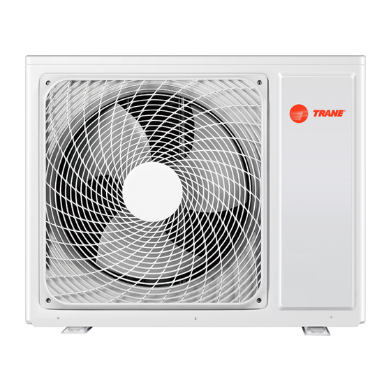
N N o o t t e e : : "Graphics in this document are for representation
only. Actual model may differ in appearance."
Advertisement
Table of Contents

Related Manuals for Trane ComfortLink II 4TWL9024A1000B


Summary of Contents for Trane ComfortLink II 4TWL9024A1000B
- Page 1 Installer’s Guide Variable Speed ComfortLink™ ™ II Side Discharge HP Models For coastal applications where units are installed within one (1) mile of salt water, epoxy coated models are recommended. These models have an 8 week lead time after order. E E p p o o x x y y C C o o a a t t e e d d M M o o d d e e l l 4TWL9024A1000B 4TWL9024A1COTB...
- Page 2 . . 18-BC100D1-1D-EN ©2021 Trane...
- Page 3 -10° F to 66° F N N o o t t e e : : See AHRI directory for approved indoor and outdoor model combinations. Only Trane coils and air handlers/furnaces are approved for use with variable speed outdoor units.
-
Page 4: Table Of Contents
Table of Contents Unit Location Considerations ....5 Start Up ........19 Setting Up the Unit . -
Page 5: Unit Location Considerations
Unit Location Considerations Table 2. Unit Dimensions (in inches) and Weight Net Weight H x D x W (in) Models (lb) 36.75 x 17 1/2 x 47 4TWL9024A1XXX 32.75 47.0 36.75 17.5 19.5 20.5 4TWL9036A1XXX 36.75 x 17 1/2 x 47 32.75 47.0 36.75... - Page 6 U U n n i i t t L L o o c c a a t t i i o o n n C C o o n n s s i i d d e e r r a a t t i i o o n n s s Table 3.
- Page 7 U U n n i i t t L L o o c c a a t t i i o o n n C C o o n n s s i i d d e e r r a a t t i i o o n n s s Table 3.
-
Page 8: Setting Up The Unit
U U n n i i t t L L o o c c a a t t i i o o n n C C o o n n s s i i d d e e r r a a t t i i o o n n s s Table 5. -
Page 9: Refrigerant Line Considerations
Refrigerant Line Considerations Table 8. Factory Charge The outdoor condensing units are factory charged with the system charge required for the outdoor condensing unit, ten (10) feet of tested connecting line, and the smallest rated indoor evaporative coil match. Always verify proper system charge via subcooling (TXV/EEV). Table 9. - Page 10 R R e e f f r r i i g g e e r r a a n n t t L L i i n n e e C C o o n n s s i i d d e e r r a a t t i i o o n n s s Table 12.
- Page 11 R R e e f f r r i i g g e e r r a a n n t t L L i i n n e e C C o o n n s s i i d d e e r r a a t t i i o o n n s s Table 15.
-
Page 12: Refrigerant Line Brazing
Refrigerant Line Brazing Table 17. Braze the Refrigerant Lines Remove caps or plugs. Use a deburring tool to debur the pipe ends. Clean both internal and external surfaces of the tubing using an emery cloth. Remove the pressure tap cap and valve core from each service valve. - Page 13 R R e e f f r r i i g g e e r r a a n n t t L L i i n n e e B B r r a a z z i i n n g g Table 17.
-
Page 14: Refrigerant Line Leak Check
R R e e f f r r i i g g e e r r a a n n t t L L i i n n e e B B r r a a z z i i n n g g Refrigerant Line Leak Check Table 18. -
Page 15: Electrical - Low Voltage
Electrical — Low Voltage Note: The use of color coded low voltage wire is recommended to simplify connections between the outdoor unit, the control, and the indoor unit. Note: The maximum total cable length for the entire comfort control communicating system is 500 ft. 18 AWG. Table 19. -
Page 16: Service Valves
Service Valves Table 21. Open the Gas Service Valve 1/4 Turn Only Important: Leak check and evacuation must be completed before opening the service valves. Counterclockwise Note: Do not vent refrigerant gases into the atmosphere. for Full Open Position Remove valve stem cap. Using a wrench, turn valve stem 1/4 turn counterclockwise to the fully open position. -
Page 17: Discharge Drive
LED Indicators — Variable Speed Side Discharge Drive L L E E D D ’ ’ S S RATE DESCRIPTION INDICATION SLOW 1 TIME PER SECOND STANDBY/IDLE MEDIUM 2 TIMES PER SECOND CALL FOR CAPACITY STATUS (GREEN) FAST 5 TIMES PER SECOND POWER UP DELAY SOLID ON TEST MODE... -
Page 18: Electrical - High Voltage
Electrical — High Voltage Table 23. High Voltage Power Supply W W A A R R N N I I N N G G L L I I V V E E E E L L E E C C T T R R I I C C A A L L C C O O M M P P O O N N E E N N T T S S ! ! F F a a i i l l u u r r e e t t o o f f o o l l l l o o w w t t h h i i s s W W a a r r n n i i n n g g c c o o u u l l d d r r e e s s u u l l t t i i n n p p r r o o p p e e r r t t y y d d a a m m a a g g e e , , s s e e v v e e r r e e p p e e r r s s o o n n a a l l i i n n j j u u r r y y , , o o r r d d e e a a t t h h . -
Page 19: Start Up
Start Up Ensure you have completed the following sections. “Refrigerant Line Brazing,” p. 12 through “,”. Set System Thermostat to OFF. Turn on disconnect(s) to apply power to the indoor and outdoor units. Wait 3 hours before starting the unit if the outdoor ambient temperature is below 85°... -
Page 20: System Charge Adjustment
System Charge Adjustment Table 26. Temperature Measurements Check the outdoor temperatures. 120° F Subcooling using “Charging Mode-Cooling” is the only recommended method of charging between 55 ° F and 120° F ambient 55° F outdoor temperature. For best results the indoor temperature should be kept between 70° F to 80°... -
Page 21: Charging And Correction Charts
Charging and Correction Charts R-410A REFRIGERANT CHARGING CHART DESIGN SUBCOOLING (°F) LIQUID TEMP (°F) LIQUID GAGE PRESSURE (PSI) Table 28. Subcool Charging Correction Charts Important: VARIABLE SPEED OUTDOOR UNITS REQUIRE THE INDOOR UNIT BE CONFIGURED FOR 400 CFM/TON 3.0 TON SUBCOOL CHARGING CHART CORRECTIONS TABLE (FOR LINE LENGTH AND RISE) 2.0 TON SUBCOOL CHARGING CHART CORRECTIONS TABLE (FOR LINE LENGTH AND RISE) Add 1°... -
Page 22: Charging The Unit
Charging the Unit Table 29. Stabilize the system Wait 20 minutes for the system condition to stabilize between adjustments. Note: When the Liquid Line Temperature and Gage Pressure 20 MIN. approximately match the chart, the system is properly charged. Remove gauges. Replace service port caps to prevent leaks. - Page 23 C C h h a a r r g g i i n n g g t t h h e e U U n n i i t t Table 32. Proper Gage Pressure Using the “System Charge Adjustment,” p. 20 adjust refrigerant level to attain proper gage pressure.
-
Page 24: Subcooling Charging Below 55º F Outdoor Temp. (In Heating Only)
Subcooling Charging Below 55º F Outdoor Temp. (In Heating Only) Table 34. Subcooling Charging Below 55º F Outdoor Temp. (In Heating Only) The Subcooling Charging method in cooling is not recommended below 55º F outdoor temperature. The only recommended method of charging at outdoor temperatures below 55º F is weighing in the charge in heating mode and referencing the refrigerant pressure curves for typical performance. -
Page 25: Communicating Display Assembly
Communicating Display Assembly (CDA) NAVIGATION • To enter and exit Technician Menus, press the Up/Down buttons simultaneously for 5 seconds. • To return to the Home Screen, press the Up/Down buttons SYSTEM STATUS simultaneously for 5 seconds. • To return to the top level of any menu, press the Left/Right buttons XXXXXXXXXXXXXXXX simultaneously for 5 seconds. - Page 26 C C o o m m m m u u n n i i c c a a t t i i n n g g D D i i s s p p l l a a y y A A s s s s e e m m b b l l y y ( ( C C D D A A ) ) 1.
-
Page 27: Checkout Procedures
Checkout Procedures The final phase of the installation is the system Checkout Procedures. The following list represents the most common items covered in a Checkout Procedure. Confirm all requirements in this document have been met. ☐ All wiring connections are tight and properly secured. ☐... - Page 28 The AHRI Certified mark indicates Trane U.S. Inc. participation in the AHRI Certification program. For verification of individual certified products, go to ahridirectory. org. Trane has a policy of continuous data improvement and it reserves the right to change design and specifications without notice. We are committed to using environmentally conscious print practices.
Need help?
Do you have a question about the ComfortLink II 4TWL9024A1000B and is the answer not in the manual?
Questions and answers