Table of Contents
Advertisement
Service Facts
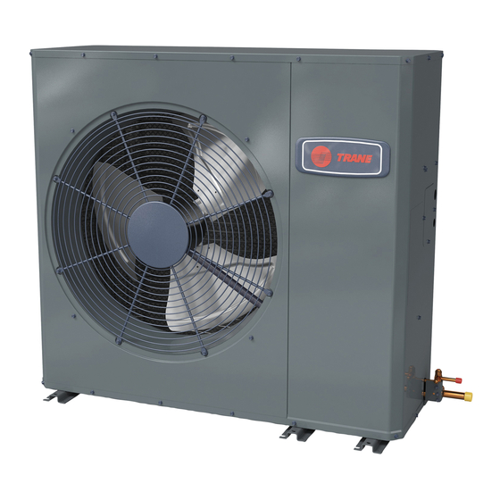
Side Discharge HP Model
For coastal applications where units are installed within one (1) mile of salt water, epoxy coated models are recommended. These models
have an 8 week lead time after order.
4TWL6036A1000A
Only qualified personnel should install and service the equipment. The installation, starting up, and servicing of heating, ventilating, and air-conditioning
equipment can be hazardous and requires specific knowledge and training. Improperly installed, adjusted or altered equipment by an unqualified person
could result in death or serious injury. When working on the equipment, observe all precautions in the literature and on the tags, stickers, and labels that
are attached to the equipment.
May 2020
E E p p o o x x y y C C o o a a t t e e d d M M o o d d e e l l
4TWL6036A1COTA
S S A A F F E E T T Y Y W W A A R R N N I I N N G G
4 4 T T W W L L 6 6 0 0 3 3 6 6 A A - - S S F F - - 1 1 F F - - E E N N
N N o o t t e e : : "Graphics in this document are for representation
only. Actual model may differ in appearance."
Advertisement
Table of Contents

Related Manuals for Trane 4TWL6036A1000A


Summary of Contents for Trane 4TWL6036A1000A
- Page 1 8 week lead time after order. E E p p o o x x y y C C o o a a t t e e d d M M o o d d e e l l 4TWL6036A1000A 4TWL6036A1COTA N N o o t t e e : : “Graphics in this document are for representation...
-
Page 2: Safety Section
. . 4TWL6036A-SF-1F-EN ©2020 Trane... -
Page 3: Product Specifications
Product Specifications OUTDOOR UNIT (a) (b) 4TWL6036A1XXXA Certified in accordance with the Air-Source Unitary Air-conditioner Equipment certification program, which is based on AHRI standard POWER CONNS. – V/PH/HZ 208–230/1/60 210/240. MIN. BRCH. CIR. AMPACITY Rated in accordance with AHRI standard 270. Calculated in accordance with Natl. - Page 4 Wiring Figure 1. 2.0, 3.0 & 3.5 Ton Models d159503p02 4TWL6036A-SF-1F-EN...
- Page 5 W W i i r r i i n n g g Figure 2. 2.0, 3.0 & 3.5 Ton Models 4TWL6036A-SF-1F-EN...
-
Page 6: Refrigerant Circuit Diagrams
Refrigerant Circuit Diagrams Figure 3. 3.0 and 3.5 Ton Models Dwg. D158717_RevB 4TWL6036A-SF-1F-EN... -
Page 7: Subcooling Charging In Cooling Between 55° F And 120° Od Ambient
Subcooling Charging in Cooling between 55° F and 120° OD Ambient Subcool Charging Correction Trane has always recommended installing Trane approved matched indoor and outdoor systems. Charts The benefits of installing approved indoor and outdoor split systems are maximum efficiency, optimum SUBCOOL CHARGING CHART CORRECTIONS TABLE (FOR LINE LENGTH AND RISE) performance and the best overall reliability. -
Page 8: Refrigerant Charging Chart
Refrigerant Charging Chart R-410A REFRIGERANT CHARGING CHART DESIGN SUBCOOLING (°F) LIQUID TEMP (°F) LIQUID GAGE PRESSURE (PSI) 4TWL6036A-SF-1F-EN... -
Page 9: Pressure Curves
Pressure Curves Figure 4. 3.0 Ton Models TEM4A0C36S41+TDR TEM4A0C36S41+TDR Cooling @ 1250 SCFM Heating @ 1250 SCFM INDOOR ENTERING INDOOR ENTERING WET BULB CURVES DRY BULB CURVES TOP TO BOTTOM TOP TO BOTTOM 71, 67, 63 AND 59 DEG F. 80, 70, AND 60 DEG F. -
Page 10: Defrost Control
Defrost Control D D e e f f r r o o s s t t C C o o n n t t r r o o l l The demand defrost control measures heat pump outdoor ambient temperature with a sensor located outside the outdoor coil. - Page 11 D D e e f f r r o o s s t t C C o o n n t t r r o o l l Table 1. Defrost Control Thermistor Table Table 2. DEMAND DEFROST QUICK SPECS THERMISTOR COMPRESSOR SCROLL...
- Page 12 D D e e f f r r o o s s t t C C o o n n t t r r o o l l Table 3. LED FAULT CODES (continued) temp. The limp mode will clear after the sensor fault is cleared.
-
Page 13: Electrical - High Voltage
Electrical — High Voltage Table 4. High Voltage Power Supply W W A A R R N N I I N N G G L L I I V V E E E E L L E E C C T T R R I I C C A A L L C C O O M M P P O O N N E E N N T T S S ! ! F F a a i i l l u u r r e e t t o o f f o o l l l l o o w w t t h h i i s s W W a a r r n n i i n n g g c c o o u u l l d d r r e e s s u u l l t t i i n n p p r r o o p p e e r r t t y y d d a a m m a a g g e e , , s s e e v v e e r r e e p p e e r r s s o o n n a a l l i i n n j j u u r r y y , , o o r r d d e e a a t t h h . -
Page 14: Low Voltage Hook-Up Diagrams
Low Voltage Hook-up Diagrams With TEM 3, 4, 6, 8 With TAM 4, 5, 7, 9 Outdoor Outdoor Thermostat Air Handler Thermostat Air Handler Unit Unit 24 VAC HOT 24 VAC HOT 24 VAC 24 VAC Common Common Blue Blue COOL/HEAT COOL/HEAT 1st STAGE... -
Page 15: Charging The Unit
Charging the Unit Table 7. Stabilize the system Wait 20 minutes for the system condition to stabilize between adjustments. Note: When the Liquid Line Temperature and Gage Pressure 20 MIN. approximately match the chart, the system is properly charged. Remove gauges. Replace service port caps to prevent leaks. - Page 16 C C h h a a r r g g i i n n g g t t h h e e U U n n i i t t Table 10. Proper Gage Pressure Adjust refrigerant level to attain proper gage pressure. Add refrigerant if the Liquid Gage Pressure is lower than the chart value.
-
Page 17: System Start-Up
System Start Up Set the system thermostat to OFF. DONE CANCEL Turn on electrical power disconnect(s) to apply power to the indoor and outdoor units. Wait one (1) hour before starting the unit if compressor crankcase heater accessory is used and the Outdoor Ambient is below 70°F. 60 MIN. -
Page 18: Troubleshooting
Troubleshooting Compressor fails to start Contactor check Is contactor engergized? Go To: Compressor won’t run (contacts closed) Wait 3 minutes and check contactor Check for 24 volts AC coil again across contactor coil Is voltage If applicable, is TDR present at Replace contactor input voltage contactor coil? - Page 19 Troubleshooting Does a resistance check show an open circuit between R and S? 4TWL6036A-SF-1F-EN...
- Page 20 The AHRI Certified mark indicates Trane U.S. Inc. participation in the AHRI Certification program. For verification of individual certified products, go to ahridirectory. org. Trane has a policy of continuous data improvement and it reserves the right to change design and specifications without notice. We are committed to using environmentally conscious print practices.
Need help?
Do you have a question about the 4TWL6036A1000A and is the answer not in the manual?
Questions and answers