SICK PowerProx Micro WTT2SL Quick Start
Hide thumbs
Also See for PowerProx Micro WTT2SL:
- Operating instructions manual (178 pages) ,
- Operating instructions manual (158 pages)
Advertisement
Quick Links
8021878.15B8 / 2019-09-09
SICK AG
Erwin-Sick-Straße 1
D-79183 Waldkirch
www.sick.com
PowerProx Micro - WTT2SL(C)
LASER CLASS 1
Laser
1
EN/IEC 60825-1:2014
IEC60825-1:2007
Maximum pulse power < 20 mW
Puls length: 5,3 ns
Wavelength: 940 nm
Complies with 21 CFR 1040.10
and 1040.11 except for deviations
pursuant to Laser Notice No. 50,
dated June 24, 2007
Q U I C K S T A R T
en
These instructions are only valid in connection with the 8021879 operating
instructions. You can find the operating instructions at www.sick.com.
de
Diese Anleitung ist ausschließlich in Verbindung mit der Betriebsanleitung
(8021879) gültig. Die Betriebsanleitung finden Sie unter www.sick.com.
it
Le presenti istruzioni sono valide solo in abbinamento alle istruzioni per l'uso
(8021879). Le istruzioni per l'uso sono a disposizione su www.sick.com.
fr
Cette notice n'est valable qu'avec la notice d'instruction (8021879). Elle est dis‐
ponible sur le site Internet www.sick.com.
es
Estas instrucciones solo son válidas junto con las instrucciones de uso
(8021879). Puede encontrar las instrucciones de uso en www.sick.com.
zh
本指南仅在结合使用操作指南 (8021879) 的情况下有效。查看操作指南可访问
www.sick.com 网页。
1
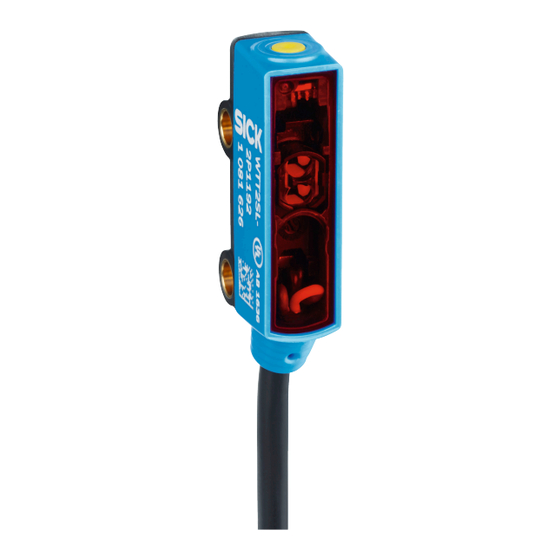
Operating and status indicators
Bedien- und Anzeigeelemente
Elementi di comando e di visualizzazione
Éléments de commande et d'affichage
1 LED indicator green: supply voltage active
Anzeige-LED grün: Versorgungsspannung aktiv
2
Indicatore LED verde: tensione di alimentazione attiva
LED d'état verte : tension d'alimentation active
LED indicador verde: tensión de alimentación activa
绿色 LED 指示灯:工作电压激活
LED indicator yellow: object detected
Anzeige-LED gelb: Objekt erkannt
Indicatore LED giallo: oggetto riconosciuto
LED d'état jaune : objet détecté
LED indicador amarillo: objeto detectado
黄色 LED 指示灯:识别到物体
2 Single teach-in button
Einfach-Teach-Taste
Semplice tasto Teach
Simple touche d'apprentissage
Tecla teach sencilla
简单示教键
2
Electrical installation
Elektrische Installation
Installazione elettrica
Installation électrique
The sensors must be connected in a voltage-free state.
Anschluss der Sensoren muss spannungsfrei erfolgen.
Il collegamento dei sensori deve avvenire in assenza di tensione.
Le raccordement des capteurs doit s'effectuer hors tension.
Los sensores deben conectarse sin tensión.
必须在无电压状态 连接传感器。
8021878.15B8 / 2019-09-09
NO
2006/42/EC
SAFETY
8021879:
Elementos de mando y visualización
操作及显示元件
Instalación eléctrica
电气安装
M12-Stecker, 4-polig
-2X329x
-2X119x
1
+(L+)
+(L+)
2
Q
Q
3
-(M)
-(M)
4
Q
Q
1 = BN
4
3
2 = WH
3 = BU
4 = BK
1
2
0.09 mm
AWG 28
Process data structure (IO-Link Version: V1.1, Process data lenght: 4 Byte)
No.
Desciptopn
Bit 0
Q
L1
Bit 1
Q
L2
Bit 2
Qint.1
Bit 3
Qint.2
Bit 4...15
empty
Bit 16...31
Analog value
3
Mounting
Montage
Montaggio
Montage
en
1
Mount sensor on suitable mounting bracket.
2
Note the sensor's maximum permissible tightening torque of 0.5 Nm.
3
Align the sensor with the object. The correct alignment can only be detected
via the LED indicators (orange indicator LED lights up).
4
Observe minimum distance from object to background.
de
1
Sensor am geeigneten Befestigungswinkel montieren.
2
Maximal zulässiges Anzugsdrehmoment des Sensors von 0.5 Nm beachten.
3
Sensor auf Objekt ausrichten. Die korrekte Ausrichtung kann nur über die
Anzeige-LEDs erkannt werden (orange Anzeige-LED leuchtet).
4
Mindestabstand von Objekt zu Hintergrund beachten.
it
1
Montare il sensore sulla staffa di fissaggio adatta.
2
Rispettare la massima coppia di serraggio consentita del sensore di 0,5 Nm.
3
Orientare il sensore sull'oggetto. L'orientamento corretto può essere rilevato
solo tramite l'indicatore LED (l'indicatore LED arancione si illumina).
4
Osservare la distanza minima dell'oggetto rispetto allo sfondo.
fr
1
Monter le capteur sur l'équerre de fixation adaptée.
2
Respecter le couple de serrage maximum autorisé du capteur de 0,5 Nm.
3
Aligner le capteur sur l'objet. Seules les LED permettent de savoir si l'aligne‐
ment est correct (LED d'état orange s'allume).
4
Respecter la distance minimale de l'objet par rapport à l'arrière-plan.
es
1
Montar el sensor en la escuadra de fijación apropiada.
2
Respetar el par de apriete máximo admisible del sensor de 0,5 Nm.
3
Orientar el sensor hacia el objeto. La alineación correcta solo se puede
detectar mediante los LED indicadores (el LED indicador naranja se
ilumina).
4
Respetar la distancia mínima entre el objeto y el fondo.
zh
1
将传感器安装在合适的安装支架上。
2
注意传感器的最大允许拧紧力矩为 0.5 Nm。
3
将传感器对准物体。仅可通过 LED 指示灯辨别校准是否正确(橙色 LED
指示灯亮起)。
4
注意目标与背景之间的最小距离。
C-2Xxx9xAxx
+(L+)
MF
-(M)
Q
/C
1
4
3
2 = WH
1
2
0.09 mm
2
AWG 28
Datatype
Byte 0: Bit 31...24
Byte 1: Bit 23...16
Byte 2: Bit 15...8
Byte 3: Bit 7...0
Boolean
Boolean
Boolean
Boolean
-
UInt16
Montaje
安装
PowerProx Micro - WTT2SL(C) | SICK
1 = BN
3 = BU
4 = BK
2
1
Advertisement

Related Manuals for SICK PowerProx Micro WTT2SL


Summary of Contents for SICK PowerProx Micro WTT2SL
- Page 1 (8021879) gültig. Die Betriebsanleitung finden Sie unter www.sick.com. Montage Le presenti istruzioni sono valide solo in abbinamento alle istruzioni per l'uso (8021879). Le istruzioni per l’uso sono a disposizione su www.sick.com. Mount sensor on suitable mounting bracket. Note the sensor's maximum permissible tightening torque of 0.5 Nm.
- Page 2 Excepción: al ajustar manualmente un valor milimétrico a través de IO-Link, recomendamos poner el punto de conmutación en el objeto. En las instrucciones de uso se describen otras opciones de aprendizaje. 8021878.15B8 / 2019-09-09 PowerProx Micro - WTT2SL(C) | SICK...
- Page 3 绿色 LED 未亮起 传感器损坏 如果电源正常,则更换传感器 黄色 LED 闪烁(非常短暂) 示教模式 检查示教模式 黄色 LED 快速闪烁(非常短 示教键按键锁已激活 禁用按键锁 暂) 黄色 LED 亮起,光路中无物 传感器和背景之间的间距过小 降低触发感应距离,参见“示 体 教”章节 光路中有物体,黄色 LED 未 传感器和物体之间的间距过大 增大触发感应距离,参见“示 亮起 或开关距离设置的过小 教”章节 8021878.15B8 / 2019-09-09 PowerProx Micro - WTT2SL(C) | SICK...
Need help?
Do you have a question about the PowerProx Micro WTT2SL and is the answer not in the manual?
Questions and answers