Advertisement
Table of Contents
- 1 Table of Contents
- 2 Safety Considerations
- 3 Parts List
- 4 System Requirements
- 5 Wiring
- 6 Dimensions − Outdoor
- 7 Clearances − Outdoor
- 8 Installation Tips
- 9 Outdoor Unit Installation
- 10 Electrical Data
- 11 Connection Diagrams
- 12 System Vacuum and Charge
- 13 Start−Up
- 14 Outdoor Unit Diagnostic Guides
- Download this manual
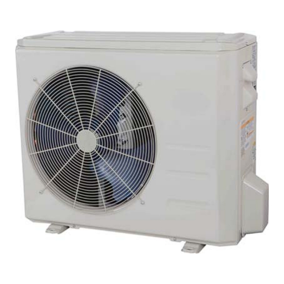
38MHRB
Outdoor Unit Single Zone Ductless System
Sizes 09 to 24
NOTE: Images are for illustration purposes only. Actual models
may differ slightly.
NOTE: Read the entire instruction manual before starting the
installation.
Installation Instructions
TABLE OF CONTENTS
. . . . . . . . . . . . . . . . . . . . . . . . . . . . . . . . . . . . . . .
. . . . . . . . . . . . . . . . . . . . . . . . . . . . . . . . . . . . . . . . . . .
. . . . . . . . . . . . . . . . . . . . . . . . . . . . . . . .
. . . . . . . . . . . . . . . . . . . . . . . . . . . . . . .
. . . . . . . . . . . . . . . . . . . . . . . . . . . . . . . . . . . . . . . .
. . . . . . . . . . . . . . . . . . . . . . . . .
. . . . . . . . . . . . . . . . . . . . . . . . . . .
. . . . . . . . . . . . . . . . . . . . . . . . . .
. . . . . . . . . . . . . . . . . . . . . . . . .
. . . . . . . . . . . . . . . . . . . . .
. . . . . . . . . . . . . . . . . . . . . . . . .
. . . . . . . . . . . . . . . . . . .
. . . . . . . . . . . . . .
PAGE
2
3
4
4
5
8
9
9
11
11
12
13
13
Advertisement
Table of Contents

Subscribe to Our Youtube Channel
Related Manuals for Carrier 38MHRBC12AA1


Summary of Contents for Carrier 38MHRBC12AA1
-
Page 1: Table Of Contents
38MHRB Outdoor Unit Single Zone Ductless System Sizes 09 to 24 Installation Instructions TABLE OF CONTENTS PAGE SAFETY CONSIDERATIONS ......PARTS LIST . -
Page 2: Safety Considerations
SAFETY CONSIDERATIONS WARNING Installing, starting up, and servicing air−conditioning equipment can be hazardous due to system pressures, electrical components, ELECTRICAL SHOCK HAZARD and equipment location (roofs, elevated structures, etc.). Failure to follow this warning could result in personal Only trained, qualified installers and service mechanics should injury or death. -
Page 3: Parts List
− The illustration above is only a sketch. Different models may be slightly different. The following units are covered in these installation instructions. Table 2—Unit Sizes SYSTEM TONS BTUh VOLTAGE - PHASE OUTDOOR MODEL 1.00 12,000 115-1 38MHRBC12AA1 Cooling Only 1.00 12,000 208/230-1 38MHRBC12AA3 1.50 18,000 208/230-1 38MHRBC18AA3 2.00... -
Page 4: System Requirements
SYSTEM REQUIREMENTS Allow sufficient space for airflow and service of the unit. See Fig. 5 for the required minimum distances between the unit, walls or ceilings. Piping IMPORTANT: Both refrigerant lines must be insulated separately. S Table 3 contains piping information for the product covered within this document. Table 3—Piping and Refrigerant Information System Size 12K (115V) -
Page 5: Dimensions − Outdoor
DIMENSIONS − OUTDOOR Table 4—Dimensions and Weights System Size Height (H) in. (mm) Width (W) in. (mm) Depth (D) in. (mm) Weight-Net lbs. (kg) (115V) 21.85(555) 30.31(770) 11.81(300) 57.8(26.2) Cooling (208/230V) 21.85(555) 30.31(770) 11.81(300) 53.8(24.4) Only (208/230V) 21.85 (555) 30.31 (770) 11.81 (300) 65.9 (29.9) (208/230V) - Page 6 DIMENSIONS − OUTDOOR (CONT) 20.24 (514) 13.11 (333) 31.50 (800) 2.76 (7 0) 2.43 (6 1.8) 0.87 (2 2) 2.43 (6 1.6) Unit: inch(mm) Fig. 3 - Size 18K Heat Pump...
- Page 7 DIMENSIONS − OUTDOOR (CONT) Unit: inch (mm) Fig. 4 - Size 24K...
-
Page 8: Clearances − Outdoor
CLEARANCES − OUTDOOR Air-inlet Air-outlet Fig. 5 - Outdoor Unit Clearance Table 5—Outdoor Unit Clearance Dimensions UNIT MINIMUM VALUE in. (mm) 24 (610) 24 (610) 24 (610) 4 (101) 4 (101) NOTE: The outdoor unit must be mounted at least 2in. (50mm) above the maximum anticipated snow depth. Fig. -
Page 9: Installation Tips
INSTALLATION TIPS Ideal installation locations include: Avoid sags in the suction line to prevent the formation of oil traps. Insulate each tube with a minimum 3/8−in. (10 mm) wall thermal pipe Outdoor Unit S A location which is convenient to installation and not exposed to insulation. - Page 10 Quantity per unit Model Number S Disconnecting means must be provided and shall be RCD Part Number located within sight and readily accessible from the air 38MHRBC12AA1 conditioner. 38MHRBC12AA3 S Connecting cable with the conduit shall be routed 38MHRBC18AA3 through hole in the conduit panel.
-
Page 11: Electrical Data
ELECTRICAL DATA Table 9—Electrical Data (Cooling Only) Outdoor Unit Size Volts-PH-Hz (115V) (208/230V) (208/230V) (208/230V) Cooling Only Max – Min* 127-104 253-187 253-187 253-187 Oper. Voltage Power Supply MOCP Compressor Outdoor Fan Motor Rated HP 0.054 0.054 0.054 0.068 Output Table 10—Electrical Data (Heat Pump) Outdoor Unit Size Volts-PH-Hz... -
Page 12: System Vacuum And Charge
SYSTEM VACUUM AND CHARGE Deep Vacuum Method CAUTION The deep vacuum method requires a vacuum pump capable of pulling a vacuum of 500 microns and a vacuum gage capable of accurately measuring this vacuum depth. The deep vacuum method is the best UNIT DAMAGE HAZARD way to assure a system is free of air and liquid water (see Fig. -
Page 13: Start−Up
START−UP OUTDOOR UNIT 1. Are there unusual noises or vibrations during operation? Test Operation Explain the Following Items to the Customer (with the aid of Perform a test operation after completing a gas leak and electrical the Owner’s Manual): safety check. See the indoor unit installation instructions and 1. - Page 14 Copyright 2018 CAC/BDP . S 7310 W. Morris St. S Indianapolis, IN 46231 Edition Date: 07/18 Catalog No: IM-38MHRB-01 Replaces: NEW Manufacturer reserves the right to change, at any time, specifications and designs without notice and without obligations.
Need help?
Do you have a question about the 38MHRBC12AA1 and is the answer not in the manual?
Questions and answers
HI WHAT KIND OF MOTHER BOARD IS IN IT to replace it thanks