
Subscribe to Our Youtube Channel
Related Manuals for Venstar EXLORER Mini


Summary of Contents for Venstar EXLORER Mini
- Page 1 7 Day Programmable Up to 2-heat & 2-cool • with Wi-Fi Local API Owner’s Manual & Installation Instructions...
- Page 2 Notice: Only peripherals complying with FCC limits may be attached to this equipment. Operation with noncompliant peripherals or peripherals not recommended by Venstar, is likely to result in interference to radio and TV reception. Changes or modifications to the product, not expressly approved by Venstar could void the user’s authority to operate the equipment.
- Page 3 être choisis afin que la puissance isotrope rayonnée équivalente (PIRE) ne est pas plus de ce qui est nécessaire pour une communication réussie. We, Venstar, declare under our sole responsibility that the device to which this declaration relates: Complies with Part 15 of the FCC Rules. Operation is...
-
Page 4: Table Of Contents
Table of Contents Installation Instructions ............1 Wire Connections ..............2 Thermostat Backplate .............3 Dip Switch Settings ..............4 Connect to Wi-Fi ..............10 Front Panel ................13 Display ..................14 Basic Operation ..............16 User Setup................17 Backlight Operation ............19 Setpoint Limits ..............20 Service Filter ..............21 Installer Setup .................22 Programming a Daily Schedule ...........29 About Advanced Features &... - Page 5 Glossary of Terms Auto-Changeover: A mode in which the thermostat will turn on the heating or cooling based on room temperature demand. Cool Setpoint: The warmest temperature that the space should rise to before cooling is turned on (without regard to deadband). Deadband: The number of degrees the thermostat will wait, once a setpoint has been reached, before energizing heating or cooling.
-
Page 6: Installation Instructions
Installation Instructions Remove and Replace the old thermostat To install the thermostat properly, please follow these step by step instructions. If you are unsure about any of these steps, call a qualified technician for assistance. • Installation tools: Small flat blade screwdriver, Phillips screwdriver, wire cutters and wire strippers. -
Page 7: Wire Connections
Installation Instructions Wire Connections If the terminal designations on your old thermostat do not match those on the new thermostat, refer to the chart below or the wiring diagrams that follow. Wire from the Install on the old thermostat Function new thermostat terminal marked connector marked... -
Page 8: Thermostat Backplate
Installation Instructions The Explorer Mini Thermostat Backplate To remove the thermostat backplate: Gently separate the display from the base by pulling from the center. 24 VAC return 2nd stage compressor relay Fan relay 24 VAC common W1/O/B 1st stage heat circuit Dry Contact 2nd stage heat circuit 1st stage compressor relay... -
Page 9: Dip Switch Settings
Installation Instructions Check Dip Switch Ensure which switch is correct for your system. Dip switches are located on the GAS/EL back of the thermostat. ELEC GAS/EL ELEC This switch (GAS or ELEC) controls how the thermostat will control the Fan (G) terminal in heating mode. - Page 10 Installation Instructions 1 Stage Heat, 1 stage Cool GAS/EL ELEC Dip Switch Settings GAS/EL ELEC Thermostat HVAC Equipment O or B...
- Page 11 Installation Instructions 2 Stage Heat, 2 Stage Cool GAS/EL ELEC Dip Switch Settings GAS/EL ELEC Thermostat HVAC Equipment O or B...
- Page 12 Installation Instructions Single Stage Heat Pump with AUX Heat GAS/EL ELEC Dip Switch Settings GAS/EL ELEC *Reversing valve choice, O or B, is dependant on the type of valve installed in the heat pump. Thermostat HVAC Equipment O or B...
- Page 13 Installation Instructions Dual Stage Heat Pump with AUX Heat GAS/EL ELEC Dip Switch Settings GAS/EL ELEC *Reversing valve choice, O or B, is dependant on the type of valve installed in the heat pump. Thermostat Aux heat will turn on with second stage of heatpump heating HVAC...
- Page 14 Installation Instructions Heat Only - with Venstar 2-Wire Kit - ACC0436 GAS/EL ELEC Dip Switch Settings GAS/EL ELEC Input 120 VAC Thermostat HVAC Equipment BLACK BLACK O or B BROWN WHITE 24 VAC Isolation ORANGE Relay ACC-0437...
-
Page 15: Connect To Wi-Fi
Skyport account setup). 3. A 6-digit code obtained from the thermostat is successfully entered into a Skyport account. 4. Successfully download and install the Venstar Skyport app on your mobile device(s). Your thermostat operates on the 2.4 Ghz, Wi-Fi b/g/n band. - Page 16 Connect to Wi-Fi Overview Wi-Fi Setup The Venstar Configurator App is needed to configure the Wi-Fi Settings of this thermostat • Download the Venstar Configurator App from your mobile device’s App Store. ICON • Open the Venstar Configurator App - Choose the Explorer Mini thermostat by sliding the thermostat pictures at the top of the apps’...
- Page 17 Connect to Wi-Fi Overview Join a Thermostat to Skyport If the thermostat is connected to the local Wi-Fi access point but not yet joined to an existing Skyport account, you may join the thermostat to the account by doing the following: 1.
-
Page 18: Front Panel
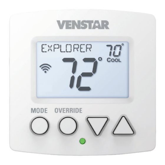
Front Panel 1 Backlit Display 2 Up/Warmer, Down/Cooler Buttons 3 Mode Button 4 Override Button 5 Heat or Cool Indicator Heat = Red, Cool = Green... -
Page 19: Display
Display Mode Indicators Selects the operational mode of the equipment. HEAT - Indicates the heating mode. COOL - Indicates the cooling mode. AUTO - Indicates the system will automatically changeover between heat and cool modes as the temperature varies. OFF - Indicates heating and cooling are turned off. Clock with Day of the Week Indicates the current time and day. - Page 20 Display 5 Occupied and Unoccupied icons Indicates the part of the time period program. 6 Setup icon Indicates the thermostat is in the setup mode. 7 Fan icon When only the FAN icon is displayed, the fan is always on. If the FAN is not on the display, then the FAN is in Auto mode and will run only when necessary to heat or cool.
-
Page 21: Basic Operation
Basic Operation Selecting Your Desired Temperature (adjusting the setpoints) Auto-Changeover Mode Pressing the WARMER or COOLER buttons in Auto mode will adjust both the heat and cool setpoints simultaneously. To adjust the heat and cool setpoints individually, choose HEAT mode to adjust the heat setpoint, and COOL mode to adjust the cool setpoint, then return to AUTO mode. -
Page 22: User Setup
User Setup TO ENTER MENUS BUTTON PRESS Setup Steps MODE & OVERRIDE for 5 seconds Table for button Time Schedule MODE & UP for 2 seconds presses that are Emergency Heat UP & OVERRIDE for 2 seconds required for Lockout Buttons MODE, UP &... - Page 23 User Setup Setting the Clock and Day (setup step 1 & 2) When your thermostat is connected to Skyport Cloud Services, the time and day of the week are controlled by Skyport. There is no local adjustment, Skyport also adjusts the time for Daylight Savings Time as well.
-
Page 24: Backlight Operation
User Setup: Backlight Operation Backlight (Setup Steps 3-6) Backlight (setup step 3) OFF - Backlight turns on only with a button press and turns off after 8 seconds. ON - Backlight is on continuously. Night Dimmer (setup step 4) - Selecting ON allows for turning off the backlight of the display during specific times of the day, usually at night. -
Page 25: Setpoint Limits
User Setup: Setpoint Limits Setpoint Limits (Setup Steps 8-10) When this feature is set to ON, the Heat and Cool Setpoints may be restricted to preset levels in Setup Steps 9 and 10. Maximum Heat Setpoint (Setup Step 9) Minimum Cool Setpoint (Setup Step 10) Lock OVERRIDE and MODE Buttons This feature is available when the thermostat is connected to... -
Page 26: Service Filter
User Setup: Service Filter These setup steps allow the user to monitor FAN runtimes and program service alerts. Service alerts appear on the display. If the thermostat is joined to a Skyport account, then the user may be alerted by Skyport Cloud Services when to change the filter. -
Page 27: Installer Setup
Installer Setup Cycles Per Hour (Setup Step 15) The Cycles Per Hour setting may limit the number of times per hour your HVAC unit may energize. For example, at a setting of 6 cycles per hour the HVAC unit will only be allowed to energize once every 10 minutes. - Page 28 Installer Setup Deadband Settings (Setup Step 18-21) The Deadband is the number of degrees or minutes that the thermostat waits before it initiates the stages of heating or cooling. 1st Stage Deadband (Setup Step 18) Specifies the temperature difference between the room temperature and the desired setpoint before the first stage of heating or cooling is allowed to turn on.
- Page 29 Installer Setup Fan Off Delay in Seconds (Setup Step 22) This feature allows the user to increase the cooling or electric strip heating efficiency of the system. The thermostat may be programmed to continue running the fan after a call for cooling or electric strip heating has been satisfied.
- Page 30 Installer Setup Comfort Recovery (Setup Step 25) With Comfort Recovery on, the thermostat will attempt to reach the OCCUPIED 1 setpoint temperature at the exact time programmed into the thermostat. Comfort Recovery, only works when the thermostat enters the OCCUPIED 1 from the UNOCCUPIED. For example, if OCCUPIED 1 is set for 6am at 72°F heating and 75°F cooling, the thermostat will turn the system on before 6am in an effort to bring the temperature to its correct setting at exactly 6am.
- Page 31 Installer Setup Dry Contact Operation Dry Contact Polarity (Setup Step 27) Open (Normally Open) - The dry contact is open until the connected device closes the circuit. ‘Idle’ ‘Active’ ‘Idle’ ‘Active’ Closed (Normally Closed) - The dry contact is closed until the connected device opens the circuit. ’...
- Page 32 Installer Setup Skyport Cloud Services (Setup Step 29) If set to ON, the thermostat may communicate and receive data from the Skyport Cloud Services. Local API (Setup Step 30) Turning on the local API allows 3rd party software to interface with the thermostat such as a home automation system.
- Page 33 Installar Setup Locking/Unlocking the Keypad To prevent unauthorized use of the thermostat, the front panel buttons may be disabled. To disable, or ‘lock’ the keypad, press and hold the MODE button. While holding the MODE button, press the WARMER and COOLER buttons together, for two seconds.
-
Page 34: Programming A Daily Schedule
Programming a Daily Schedule Programming a Daily Schedule To enter Time Period Programming screens, MODE Press and hold MODE and UP until the scrolling prompt appears. Select the number of Occupied time periods – Press the Warmer or Cooler buttons to choose the maximum number (up to 3 maximum) of Occupied time periods in a day. - Page 35 Programming a Daily Schedule Continued Adjust the Unoccupied Heat Setpoint – Press the Warmer or Cooler button to adjust the Heating setpoint for times when the thermostat is in Unoccupied. The following steps determine when the Occupied period(s) will be active. Enable Occupied 1 –...
-
Page 36: About Advanced Features & Operation
About Advanced Features & Operation Deadband Operation Controls up to two Heat and two Cool stages. The 1st Stage of heat or cool is turned on when: (A) The temperature spread from the setpoint is equal to or greater than: the setpoint plus the 1st stage deadband. This 1st stage dead- band is adjustable from 1-6 degrees and the default is two degrees. - Page 37 About Advanced Features & Operation Emergency Heat Only available if you have a Heat Pump installed. To initiate the Emergency Heat feature, press the OVERRIDE button. While holding the OVERRIDE button press the UP button, for two seconds. The display will read ‘EM HEAT’...
- Page 38 About Advanced Features & Operation Calibration Under normal circumstances it will not be necessary to adjust the calibration of the temperature sensor. If calibration is required, please contact a trained HVAC technician to correctly perform the following procedure. MODE Place the thermostat in the OFF mode. Press and hold the MODE button.
- Page 39 About Advanced Features & Operation Factory Defaults If, for any reason, you desire to return all the stored settings back to the factory default settings, follow the instructions below. WARNING: This will reset all Time Period and Advanced Programming to the default settings. Any information entered prior to this reset will be permanently lost.
- Page 40 About Advanced Features & Operation (Continued) You now have the option of restoring the factory settings to just Wi-Fi (Wi-Fi), or just the thermostat (STAT), or both the thermostat and Wi-Fi (ALL). C. Select one of the above options using the Up or Down buttons.
-
Page 41: Advanced Setup Table
Advanced Setup Table FD = Factory Default Setting Step# Description Pg# Range Set Clock 12A - 12A Set Day of the Week Monday - Sunday Backlight On, Off, 6pm-6am Night Dimmer On/Off Night Dimmer Start Time 12A - 12A 8:00PM Night Dimmer Stop Time 12A - 12A 6:00AM... - Page 42 Warranty One-Year Warranty - This Product is warranted to be free from defects in material and workmanship. If it appears within one year from the date of original installation, whether or not actual use begins on that date, that the product does not meet this warranty, a new or remanufactured part, at the manufacturer’s sole option to replace any defective part, will be provided without charge for the part itself provided the defective part is returned to the distributor through a qualified servicing dealer.
- Page 43 Printed on recycled paper. P/N 88-1195 rev.2 02/19...
Need help?
Do you have a question about the EXLORER Mini and is the answer not in the manual?
Questions and answers