Table of Contents
Advertisement
Advertisement
Table of Contents

Related Manuals for Venstar T3900


Summary of Contents for Venstar T3900
- Page 2 Notice: Only peripherals complying with FCC limits may be attached to this equipment. Operation with noncompliant peripherals or peripherals not recommended by Venstar, is likely to result in interference to radio and TV reception. Changes or modifications to the product, not expressly approved by Venstar could void the user’s authority to operate the equipment.
- Page 3 être choisis afin que la puissance isotrope rayonnée équivalente (PIRE) ne est pas plus de ce qui est nécessaire pour une communication réussie. We, Venstar, declare under our sole responsibility that the device to which this declaration relates: Complies with Part 15 of the FCC Rules. Operation is...
- Page 4 Glossary of Terms Auto-Changeover: A mode in which the thermostat will turn on the heating or cooling based on room temperature demand. Cool Setpoint: The warmest temperature that the space should rise to before cooling is turned on (without regard to deadband). Deadband: The number of degrees the thermostat will wait, once a setpoint has been reached, before energizing heating or cooling.
-
Page 5: Table Of Contents
Table of Contents Table of Contents GET TO KNOW YOUR THERMOSTAT Get to Know Your Thermostat ............1 Quick Start ..................6 INTALLATION INSTRUCTIONS Installation Instructions ..............9 Sample Wiring Diagrams .............. 13 Test Operation ................16 USER SETUP Backlight Operation ..............17 Scrolling Display Options ............. -
Page 6: Get To Know Your Thermostat
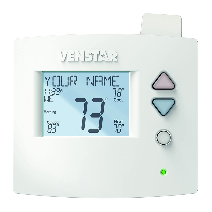
Get To Know Your Thermostat Optional Wireless Module Backlit, Scrolling Display Backlit Cooler & Warmer Buttons Backlit LCD Display Mode Button Heat or Cool Demand Indicator Red = Heat, Green = Cool Setup Buttons Behind Door... - Page 7 Get To Know Your Thermostat Setup Buttons...
- Page 8 Get To Know Your Thermostat Display Features Program ONOFF 2nd3rd 18:88 Stage Setup Step Day Night Morning Evening Fan On Outdoor The scrolling display will be used to help you easily navigate the setup screens in the thermostat. Clock with Day of the Week Indicates the current time and day.
- Page 9 Get To Know Your Thermostat Display Features Program ONOFF 2nd3rd 18:88 Stage Setup Step Day Night Morning Evening Fan On Outdoor Desired Set Temperature Indicates desired room temperature(s). Also displays the highest and lowest temperatures for the day. Morning, Day, Evening & Night icons Indicates the day part of the time period program.
- Page 10 Get to know your thermostat Display Features Program ONOFF 2nd3rd 18:88 Stage Setup Step Day Night Morning Evening Fan On Outdoor AuxHeat icon Indicates 2nd stage electric strip heat is being used when the thermostat is programmed for Heat Pump operation. Only the Aux icon will appear during Cool to Dehumidify to indicate Reheat operation.
-
Page 11: Quick Start
Quick Start During Setup and Programming Press the WARMER or COOLER buttons to modify the selection. Press the MODE button to advance and confirm through the setup steps. Setting the Clock and Day* *Not available when connected to a Skyport Account Press the SET CLOCK button. - Page 12 Quick Start Selecting your desired temperature AUTO-CHANGEOVER MODE - Pressing the WARMER or COOLER buttons in Auto mode will adjust both the heat and cool setpoints simultaneously. To adjust heat and cool setpoints individually, choose HEAT mode to adjust the heat setpoint and COOL mode to adjust the cool setpoint, then return to AUTO mode.
- Page 13 Quick Start OVERRIDE Viewing the Temperature Sensors OUTDOOR OUTDOOR TEMP - Press the OUTDOOR button to view the current outdoor temperature. The high and low temperatures for the day will also be displayed. The high and low temperatures reset at 12:00 am. Press the OUTDOOR button again to return to normal operation.
-
Page 14: Installation Instructions
Installation Instructions Remove and Replace the old thermostat To install the thermostat properly, please follow these step by step instructions. If you are unsure about any of these steps, call a qualified technician for assistance. • Assemble tools: Flat blade screwdriver, wire cutters and wire strippers. -
Page 15: Wire Connections
Installation Instructions Wire Connections If the terminal designations on your old thermostat do not match those refer to the chart below or the wiring on the new thermostat, diagrams that follow. Wire from the Install on the old thermostat Function new thermostat terminal marked connector marked... - Page 16 Installation Instructions The Voyager Thermostat Backplate To remove the thermostat backplate: Gently separate the display from the base by pulling first from one side, then the other until the two pieces unsnap. A small screwdriver may be used, very carefully, to start seperating the two pieces.
- Page 17 Installation Instructions Check Dip Switch Ensure which switch is correct for your system. Dip switches are located on the back of the thermostat. ELEC ELEC GAS/EL GAS/EL 1. When GAS/EL or HP is set for GAS/EL: ELEC ELEC This switch (GAS or ELEC) controls how the thermostat will control the Fan (G) terminal in heating mode.
-
Page 18: Sample Wiring Diagrams
Installation Instructions Sample Wiring Diagrams Conventional Heating and Cooling Systems 3 Wire, Heat Only 4 Wire, Cool Only Residential & Commercial 1 Stage Heating Residential & Commercial 1 Stage Cooling. with no Fan. 24VAC Power 24VAC Power 24VAC Common 24VAC Common 1st Stage Cool W1/O/B 1st Stage Heat... -
Page 19: Heat Pump Systems
Installation Instructions Sample Wiring Diagrams Heat Pump Systems 5 Wire, 1 Stage Cooling, 1 Stage Heat 6 Wire, 1 Stage Cooling, 2 Stage Heat Residential & Commercial Heat Pump with Residential & Commercial Heat Pump with ‘O’ Reversing Valve ‘O’ Reversing Valve 24VAC Power 24VAC Power 24VAC Common... - Page 20 Installation Instructions Sample Wiring Diagrams Heat Pump Systems with Dual Fuel 7 Wire, 2 Stage Cooling, 3 Stage Heat Residential & Commercial Heat Pump with ‘O’ Reversing Valve and Fossil Fuel furnace. Heat Pump 24VAC Power 24VAC Common W1/O/B Reversing Valve 3rd Stage Heat Setup Step 24 is set to 2 (connected to furnace)
-
Page 21: Test Operation
Installation Instructions Test Operation The technician setup is a diagnostic feature that enables testing of all outputs. To enter Technician Setup, press and hold the SETUP button for 5 seconds until all the icons appear. Follow the next steps to view settings and test equipment. 1. -
Page 22: User Setup Backlight Operation
User Setup: Backlight Operation How to Change Settings in the Setup Screens To enter Advanced Setup, press the SETUP button, then press MODE. Use the WARMER or COOLER buttons to adjust the value of your selection. Press MODE to advance to the next setup step. Press SETUP again to leave the setup screens. WARMER Setup MODE... -
Page 23: Scrolling Display Options
User Setup: Scrolling Screen and Display Options Scrolling Display Method (Setup Step 21) This option allows the user to choose how the scrolling text is displayed. Options are: Scrolling Non-Scrolling Scroll Letters Slow Whole Words Slow Scroll Letters Fast Whole Words Fast Scroll Words Slow Words Centered Slow Scroll Words Fast... -
Page 24: Programming Vacation/Away
User Setup Vacation & Away Settings The Vacation feature allows the thermostat to use temporary, VACATION energy saving setpoints without having to change regular programming. The HOME/AWAY feature allows for a one button press to bring in your stored unoccupied vacation settings. A subsequent press HOME/ of the HOME/AWAY button restores the last used comfort settings. -
Page 25: Wireless Modules
They are: 1. Wi-Fi Module 2. Z-Wave Module 3. ZigBee Module 4. Venstar RF Module VENSTAR RF Module Please follow the instructions included with the wireless accessory to start the linking process. The general instructions are below. Press the Accessory Setup button to enter the linking/un-linking mode. - Page 26 User Setup - Wireless Modules Wi-Fi Module Wi-Fi Module ACCESSORY STATUS ACCESSORY SETUP Please follow the instructions included with the Wi-Fi module to connect to an Access Point or view status. The general instructions are below. Wi-Fi Module If the is present on the display then the thermosat is connected to the Wi-Fi Access Point.
- Page 27 User Setup - Wireless Modules Z-Wave Module Z-Wave Module ACCESSORY STATUS ACCESSORY SETUP Please follow the instructions included with the Z-Wave module to join the Network or view status. The general instructions are below. Z-Wave Module Press the Accessory Status button to view the status of the thermostat’s connection to the Network.
- Page 28 User Setup - Wireless Modules ZigBee Module ZigBee Module ACCESSORY STATUS ACCESSORY SETUP Please follow the instructions included with the ZigBee module to join the Network or view status. The general instructions are below. ZigBee Module Press the Accessory Status button to view the status of the thermostat’s connection to the Network.
-
Page 29: Service Filter
User Setup - Service Filter These setup steps allow the user to monitor equipment runtimes and program service alerts. Service alerts are displayed in the scrolling marquee. Runtime hours or days appear in the clock display. Setup Step FAN ON OUTDOOR˚... -
Page 30: Runtimes
User Setup - Runtimes To view, set, or reset System Runtimes, press the SETUP button, then press MODE. Press MODE to advance to the desired setup step. Use the WARMER or COOLER buttons to adjust the value of your selection. Press SETUP again to leave the setup screens. -
Page 31: Time Period Programming
User Setup - Time Period Programming Selecting Your Time Period Schedule (setup step 1) This thermostat may be configured to be programmable or non programmable. 7 Day Program - Allows all seven days to be programmed independently. Non Program - No advanced time period programming available. 1 Day Program - Allows one 24 hour day to be programmed. - Page 32 User Setup - Time Period Programming This thermostat features four programmable time periods per 24 hour day: Morning, Day, Evening, and Night. The start time for each time period is adjustable. The stop time for each time period is the start time for the next period.
-
Page 33: Installer Setup
Installer Setup How to Change Settings in the Setup Screens To enter Advanced Setup, press the SETUP button, then press MODE. Use the WARMER or COOLER buttons to adjust the value of your selection. Press MODE to advance to the next setup step. Press SETUP again to leave the setup screens. -
Page 34: Setpoint Limits
Installer Setup Setpoint Limits (setup step 22) When this feature is set to ON, the heat and cool setpoints can be restricted to preset levels, set in steps 19 and 20. Maximum Heat Setpoint (Setup Step 23) - (35˚ - 99˚). Minimum Cool Setpoint (Setup Step 24) - (35˚... -
Page 35: Timers And Deadbands
Installer Setup Deadband Settings (setup steps 32 - 41) The Deadband is the number of degrees or minutes that the thermostat waits before it initiates the stages of heating or cooling. 1st Stage Deadband (Setup Step 32) - Specifies the minimum temperature difference between the room temperature and the desired setpoint before the first stage of heating or cooling is allowed to turn on. -
Page 36: Programming Fan Operation
Installer Setup Programming the Fan (setup steps 42 - 45) (This feature not available on all models) Fan Program (Setup Step 42) - This feature allows the fan to be programmed to turn on automatically for a specified amount of time during the day. If this feature is set to ON, the next three steps will appear. -
Page 37: Humidification & Dehumidification
Installer Setup Humidity and Dehumidity (setup steps 48 -54, 79-81) Humidity Only With Heat (Setup Step 48) - When this step is set to ON, Humiditywill not run without a demand for Heat. Fan With Humidity Demand (Setup Step 49) - Specifies if the fan should be turned on with a demand for Humidity. -
Page 38: Dual Fuel Operation
Installer Setup Lockout Heat Pump on Outdoor Temp (setup steps 55 - 56) This feature stops the heat pump from running below a specified outdoor temperature, where the heat pump has become inefficient or could damage equipment. A local outdoor sensor must be used for this feature to work. Lockout Heat Pump With Outdoor Temp (setup step 55) - When set to ON, the Heat Pump Lockout feature is enabled. -
Page 39: Remote Sensor Operation
Installer Setup Dual Fuel (cont.) Setup steps 60-62 will only appear if step 59 is set to ON. Dual Fuel Changeover on Outdoor Temp (setup step 60) - ON: the change from Heat Pump to a fossil fuel source of heat will be based on outdoor temperature. -
Page 40: Auxiliary Output
Installer Setup Auxiliary Output The Voyager Thermostat is equipped with a programmable auxiliary output. This output can be configured to be controlled from a variety of sources. Aux Output Polarity (setup step 65) Specifies if the Auxiliary output will be Open (Normally Open) or Closed (Normally Closed). - Page 41 Installer Setup Auxiliary Output Programming By Temp If TEMP is selected for the Aux Output, the following setup steps will appear: Aux Output Temp Source (setup step 72) - Specifies what temperature source will be monitored for controlling the programmable output. The options are: Thermostat - Temperature is monitored from the thermostat sensor.
-
Page 42: Dry Contact Operation
Installer Setup Free Cooling (setup steps 74 - 75) To use Free Cooling, setup step 66 must be set to ‘FREE COOLING’ . Free Cooling is an energy saving way to boost the efficiency of your air conditioning system by bringing in fresh air from the outside. The installation of a Free Cooling damper and outdoor temperature sensor are required. -
Page 43: Factory Defaults
Installer Setup Resetting the Thermostat to the Factory Default Settings (for default values see page 41, Advanced SetupTable) If, for any reason, you desire to return all the stored settings back to the factory default settings, follow the instructions below. WARNING: This will reset all Time Period and Advanced Programming to the default settings. - Page 44 Installer Setup Locking/Unlocking the Keypad To prevent unauthorized use of the thermostat, the front panel buttons may be disabled. To disable, or ‘lock’ the keypad, press and hold the MODE button. While holding the MODE button, press the WARMER and COOLER buttons together.
-
Page 45: Technician Setup
Technician Setup To enter Technician Setup, press and hold the SETUP button for 10 seconds. After all the icons appear, press MODE. The version number of the thermostat will appear in the scrolling text. Press MODE to advance to the next step. Use the WARMER or COOLER buttons to adjust the value of your selection. -
Page 46: Advanced Setup Table
Advanced Setup Table Df = Factory Default Setting Step# Description Pg# Range Prog Mode Non, 1 Day, 5/2 Day, 7 Day 7 Available Modes Heat/Cool/Auto/Off, Heat/Cool/ Heat/Cool/Off, Heat/Off, Auto/Off Cool/Off Backlight On, Off, 6pm-6am Off thru 7 levels of brightness Backlight Level Level 5 Night Dimmer... - Page 47 Advanced Setup Table Df = Factory Default Setting Step# Description Pg# Range 3rd Stage Deadband 0 - 10 Degrees 4th Stage Deadband 0 - 10 Degrees Minutes Between 1st and 2nd Stage 0 - 60 Minutes Minutes Between 2nd and 3rd Stage 30 0 - 60 Minutes Minutes Between 3rd and 4th Stage 0 - 60 Minutes...
- Page 48 Advanced Setup Table Df = Factory Default Setting Step# Description Pg# Range Aux Output Trigger Point Temp 0 - 120 Degrees Free Cooling with A/C With A/C, Without A/C With A/C Free Cooling Usuable Temp 40 - 80 Degrees Comfort Recovery On, Off Dry Contact Polarity Open, Closed...
-
Page 49: Troubleshooting
Troubleshooting • SYMPTOM: The air conditioning does not attempt to turn on. CAUSE: The compressor timer lockout may prevent the air conditioner from turning on for a period of time. REMEDY: Consult the Owner’s Manual in the Installer Setup section to defeat the Cycles Per Hour (page 29). -
Page 50: Index
Index mode, 1, 6 mode, 2, 5 outdoor, 1, 8 overcool, see Overcool program, 1, 26 program, see Program set clock, 2, 6 runtime, see Runtime setup, 17 setpoint, 3, 6, 20 vacation, 2, 19 to dehumidify, see up (warmer), 1, 7 Dehumidify Alerts see Runtime... - Page 51 Index Delay Energy Watch fan-off, see Fan cool, 25 time between stages, heat, 25 see Time Delay Differential Gas/Electric Furnace heat and cool, 29 jumper, 12 Disabled Keypad Green Cool Indicator, 1 Factory Defaults see Keypad Lockout settings, 41, 42, 43 Drain Pan Overflow resetting, 38 Alarm, see Dry...
- Page 52 Index Heat Pump Mode, 3, 6, 7, 28 AuxHeat, 5, 12, 19, 25 Multi-stage AUXHeat Lockout, 33 Operation, 29, 30 emergency heat, 19 jumper setting, 12 LCD, 3, 4, 5 multi-stage, 14, 15 icon, 5 Language, 17 Humidity Locked Indication, see Keypad Lockout setpoint, 8 Non-Programmable...
- Page 53 Index viewing, cool, 25 heat, 25 humidification, 25 UV lamp, 25 Pan, Service Reheat see Dry Contact during cool to dehumidify, 32 Polarity, see Dry Contact electric heating, 32 Program Remote Sensor Copy, 27 averaging with Schedule daily schedule, 26, 27 Thermostat, 34 Daily, see Program mode, 28...
- Page 54 Index Technician Setup, 16, 40 UV Light W3, see Jumpers resetting, 25 Terminal, Misc. runtime, see Runtime Wireless Module, 20 see MISC setting, see Runtime Warranty, 46 Thermostat Sensor averaging, 34 Wi-Fi, 21 calibrate, 16, 40 Three Stage Heat, 14, 30 Vacation Time, see Clock button, see Buttons...
- Page 55 Warranty One-Year Warranty - This Product is warranted to be free from defects in material and workmanship. If it appears within one year from the date of original installation, whether or not actual use begins on that date, that the product does not meet this warranty, a new or remanufactured part, at the manufacturer’s sole option to replace any defective part, will be provided without charge for the part itself provided the defective part is returned to the distributor through a qualified servicing dealer.
- Page 56 Programming Worksheet - see page 23 DAY PERIOD START TIME COOL HEAT Morning Evening Night Morning Copy Mon to Tues Evening Night Morning Copy Tues to Wed Evening Night Morning Copy Wed to Thurs Evening Night Morning Copy Thurs to Fri Evening Night Morning...
- Page 57 Patent Pending Printed on recycled paper. P/N 88-1015 Rev. 1 8/15...
Need help?
Do you have a question about the T3900 and is the answer not in the manual?
Questions and answers