Table of Contents
Advertisement
Advertisement
Table of Contents

Subscribe to Our Youtube Channel
Related Manuals for Venstar COMMERCIAL T4800


Summary of Contents for Venstar COMMERCIAL T4800
- Page 2 CAUTION Follow the Installation Instructions before proceeding. Set the thermostat mode to “OFF” prior to changing settings in setup or restoring Factory Defaults. This device complies with Part 15 of the FCC Rules. Operation is subject to the following two conditions: (1) this device may not cause harmful interference, and (2) this device must accept any interference received, including interference that may cause undesired operation.
- Page 3 Glossary of Terms Auto-Changeover: A mode in which the thermostat will turn on the heating or cooling based on room temperature demand. Cool Setpoint: The warmest temperature that the space should rise to before cooling is turned on (without regard to deadband). Deadband: The number of degrees the thermostat will wait, once a setpoint has been reached, before energizing heating or cooling.
-
Page 4: Table Of Contents
Table of Contents GET TO KNOW YOUR THERMOSTAT Get to Know Your Thermostat ............1 Quick Start ..................6 INTALLATION INSTRUCTIONS ............8 Sample Wiring Diagrams .............. 12 Test Operation ................15 USER SETUP Backlight Operation ..............16 Scrolling Display Options ............. 17 Thermostat Display Options............ -
Page 5: Get To Know Your Thermostat
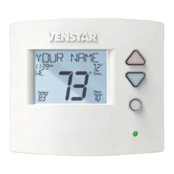
Get To Know Your Thermostat Optional Wireless Module Backlit, Scrolling Display Backlit Cooler & Warmer Buttons Backlit LCD Display Override Button Heat or Cool Demand Indicator Red = Heat, Green = Cool Programming Port Setup Buttons Behind Door... - Page 6 Get To Know Your Thermostat Setup Buttons...
- Page 7 Get To Know Your Thermostat Display Features Program ONOFF 2nd3rd 18:88 Unoccupied123 Stage Setup Step Day Night Morning Evening Override Fan On Outdoor The scrolling display will be used to help you easily navigate the setup screens in the thermostat. Clock with Day of the Week Indicates the current time and day.
- Page 8 Get To Know Your Thermostat Display Features Progr m ONOFF 2nd3rd 18:88 Unoccupied123 Stage Setup Step Day Night Morning Evening Override Fan On Outdoor Desired Set Temperature Indicates desired room temperature(s). Also displays the highest and lowest temperatures for the day. Occupied &...
- Page 9 Get To Know Your Thermostat Display Features Program ONOFF 2nd3rd 18:88 Unoccupied123 Stage Setup Step Day Night Morning Evening Override Fan On Outdoor AuxHeat icon Indicates 2nd stage electric strip heat is being used when the thermostat is programmed for Heat Pump operation. Only the Aux icon will appear during Cool to Dehumidify to indicate Reheat operation.
-
Page 10: Quick Start
Quick Start During Setup and Programming: Press the WARMER or COOLER buttons to modify the selection. Press the MODE button to advance and confirm through the setup steps. WARMER Setting the Clock and Day MODE Clock COOLER Not available when Wi-Fi enabled Press the SET CLOCK button. - Page 11 Quick Start NOTE: Override may only be Using the Override Button used when the thermostat is UNOCCUPIED OPERATION - set to PROGRAM ON. OVERRIDE During programmed, unoccupied periods, pressing the OVERRIDE button will force the thermostat into Occupied OUTDOOR 1 settings for 30 minutes. Each press of the OVERRIDE button will add another 30 minutes of time for up to 4 hours.
- Page 12 Installation Instructions Remove and Replace the old thermostat To install the thermostat properly, please follow these step by step instructions. If you are unsure about any of these steps, call a qualified technician for assistance. • Assemble tools: Flat blade screwdriver, wire cutters and wire strippers.
- Page 13 Installation Instructions Wire Connections If the terminal designations on your old thermostat do not match those refer to the chart below or the wiring on the new thermostat, diagrams that follow. Wire from the Install on the old thermostat Function new thermostat terminal marked connector marked...
- Page 14 Installation Instructions The Voyager Thermostat Backplate To remove the thermostat backplate: Using the Finger Pull Areas, pull the front housing away from the backplate. OUTDOOR W1/O/B SENSOR REMOTE SENSOR CONTACT FAULT Backplate Front Housing Finger Pull Areas 24 VAC return 24 VAC common Fan relay OUTDOOR...
- Page 15 Installation Instructions Explanation of Thermostat Jumpers Jumpers are located on the back of the thermostat GAS E EC RV=O GAS/ELEC RV=O OUTDOOR W1 O/B SENSO R MOT SENSO HEATPUMP RV=B ELEC CONTACT FAUL DEHUM This jumper configures the thermostat to control a GAS/ELEC conventional gas/electric system or a heat pump.
-
Page 16: Sample Wiring Diagrams
Installation Instructions Sample Wiring Diagrams Conventional Heating and Cooling Systems 3 Wire, Heat Only 4 Wire, Cool Only Residential & Commercial 1 Stage Heating Residential & Commercial 1 Stage Cooling. with no Fan. 24VAC Power 24VAC Power 24VAC Common 24VAC Common 1st Stage Cool W1/O/B 1st Stage Heat... - Page 17 Installation Instructions Sample Wiring Diagrams Heat Pump Systems 5 Wire, 1 Stage Cooling, 1 Stage Heat 6 Wire, 1 Stage Cooling, 2 Stage Heat Residential & Commercial Heat Pump with Residential & Commercial Heat Pump with ‘O’ Reversing Valve ‘O’ Reversing Valve 24VAC Power 24VAC Power 24VAC Common...
- Page 18 Installation Instructions Sample Wiring Diagrams Dry Contact and Aux Output W1/O/B OUTDOOR SENSOR REMOTE SENSOR CONTACT FAULT Accessory such as a Time Clock or door switch...
-
Page 19: Test Operation
Installation Instructions: Test Operation The Voyager thermostat has a diagnostic feature that enables testing of all outputs. This feature is contained in Technician Setup. To enter Technician Setup, press and hold the SETUP button for 5 seconds until all the icons appear. Follow the next steps to view settings and test equipment. 1. -
Page 20: User Setup Backlight Operation
User Setup - Backlight Operation How to Change Settings in the Setup Screens To enter Advanced Setup, press the SETUP button, then press MODE. Use the WARMER or COOLER buttons to adjust the value of your selection. Press MODE to advance to the next setup step. -
Page 21: Scrolling Display Options
User Setup - Scrolling Screen & Display Options Scrolling Display Method (Setup Step 19) This option allows the user to choose how the scrolling text is displayed. Options are: Scrolling Non-Scrolling Scroll Letters Slow Whole Words Slow Scroll Letters Fast Whole Words Fast Scroll Words Slow Words Centered Slow... - Page 22 User Setup (This feature not available on all models) Holiday VACATION The Holiday feature allows the thermostat to use temporary, energy saving setpoints without having to change regular programming. Press the HOLIDAY button to enter Vacation programming. Use the WARMER and COOLER buttons to choose the number of days desired to run the Vacation feature.
-
Page 23: Rf Module
Voyager theremostats may use 1 of 4 different types of modules. They are: 1. Wi-Fi Module 2. Z-Wave Module 3. ZigBee Module 4. Venstar RF Module VENSTAR RF Module Please follow the instructions included with the wireless accessory to start the linking process. The general instructions are below. -
Page 24: Wi-Fi Module
User Setup Wi-Fi Module Wi-Fi Module ACCESSORY STATUS ACCESSORY SETUP Please follow the instructions included with the Wi-Fi module to connect to an Access Point or view status. The general instructions are below. Wi-Fi Module If the is present on the display then the thermosat is connected to the Wi-Fi Access Point. - Page 25 User Setup Z-Wave Module Z-Wave Module ACCESSORY STATUS ACCESSORY SETUP Please follow the instructions included with the Z-Wave module to join the Network or view status. The general instructions are below. Z-Wave Module Press the Accessory Status button to view the status of the thermostat’s connection to the Network.
- Page 26 User Setup ZigBee Module ZigBee Module ACCESSORY STATUS ACCESSORY SETUP Please follow the instructions included with the ZigBee module to join the Network or view status. The general instructions are below. ZigBee Module Press the Accessory Status button to view the status of the thermostat’s connection to the Network.
-
Page 27: System Runtimes
User Setup - System Runtimes These setup steps allow the user to monitor equipment runtimes and program service alerts. Service alerts are displayed in the scrolling marquee. Runtime hours or days appear in the clock display. Setup Step OUTDOOR Press and hold OUTDOOR to clear service alert messages from the scrolling marquee. - Page 28 User Setup - System Runtimes To view, set, or reset System Runtimes, press the SETUP button, then press MODE. Press MODE to advance to the desired setup step. Use the WARMER or COOLER buttons to adjust the value of your selection. Press SETUP again to leave the setup screens.
-
Page 29: Time Period Programming
User Setup - Time Period Programming To enter Time Period Programming HOLD TO SET screens, Press and hold PROGRAM until the scrolling prompt appears. OFF - Time Period Program is off. RUN - Time Period Program is running. HOLD TO SET - Press and hold PROGRAM to make Time Period HOLD TO SET Programming changes. -
Page 30: Installer Setup
Installer Setup How to Change Settings in the Setup Screens To enter Advanced Setup, press the SETUP button, then press MODE. Use the WARMER or COOLER buttons to adjust the value of your selection. Press MODE to advance to the next setup step. Press SETUP again to leave the setup screens. - Page 31 Installer Setup Setpoint Limits (setup step 20) This feature allows the user to set 4 different levels of security: (0 - 3). No Setpoint Limits (0) - When this level is selected, no restrictions are activated. Use Setpoint Limits (1) - When this level is selected, the heat and cool setpoints can be restricted to preset levels, set in setup steps 21 and 22.
- Page 32 Installer Setup Deadband Settings (setup steps 27 - 36) The Deadband is the number of degrees or minutes that the thermostat waits before it initiates the stages of heating or cooling. 1st Stage Deadband (setup step 27) - Specifies the minimum temperature difference between the room temperature and the desired setpoint before the first stage of heating or cooling is allowed to turn on.
-
Page 33: Comfort Recovery Operation
Installer Setup Fan Mode (setup step 5) This feature allows the following options: Fan Fan Auto - If Fan Auto is selected, the fan will run while there is a call for heating or cooling. Fan On - If Fan On is selected, the fan will run continuously during Occupied Mode and turn off during Unoccupied Mode. -
Page 34: Dry Contact Operation
Main Menu Buttons - Information Dry Contact Operation (setup step 69 - 72) Dry Contact Polarity (setup step 69) Open (Normally Open) - The dry Closed (Normally Closed) - The dry contact is open until the connected contact is closed until the connected device closes the circuit. -
Page 35: Fahrenheit Or Celsius
Installer Setup Fahrenheit or Celsius (setup step 55) This feature allows the thermostat to display temperature in Fahrenheit or Celsius. Press Outdoor To Clear All Messages (setup step 76) This feature allows the user to clear all current error messages from the display. -
Page 36: Locking / Unlocking Keypad
Installer Setup Locking/Unlocking the Keypad To prevent unauthorized use of the thermostat, the front panel buttons may be disabled. To disable, or ‘lock’ the keypad, press and hold the MODE button. While holding the MODE button, press the WARMER and COOLER buttons together. - Page 37 Installer Setup Resetting the Thermostat to the Factory Default Settings (for default values see page 34) If, for any reason, you desire to return all the stored settings back to the factory default settings, follow the instructions below. WARNING: This will reset all Time Period and Advanced Programming to the default settings.
-
Page 38: Technician Setup
Technician Setup To enter Technician Setup, press and hold the SETUP button for 5 seconds. After all the icons appear, press MODE. The version number of the thermostat will appear in the scrolling text. Press MODE to advance to the next step. Use the WARMER or COOLER buttons to adjust the value of your selection. -
Page 39: Troubleshooting
Troubleshooting • SYMPTOM: The air conditioning does not attempt to turn on. CAUSE: The compressor timer lockout may prevent the air conditioner from turning on for a period of time. REMEDY: Consult the Owner’s Manual in the Installer Setup section to defeat the Cycles Per Hour (page 22). -
Page 40: Advanced Setup Table
Advanced Setup Table Df = Factory Default Setting Step# Description Pg# Range Prog Mode Non, 1, 5/1/1*, 7* Available Modes Heat/Cool/Auto/Off Heat/Cool/ Heat/Cool/Off,Heat/Off, Auto/Off Cool/Off Backlight On, Off, 6pm-6am 6pm-6am Backlight Level Off-7 levels of brightness Level 5 Fan Mode Auto, On Auto Current Service Filter Runtime Hours 18... - Page 41 Main Menu Buttons - Settings Df = Factory Default Setting Step# Description Pg# Range Minutes Between 3rd and 4th Stage 0-60 2nd Stage Turnoff Point Deadband, Setpoint Deadband 3rd Stage Turnoff Point Deadband, Setpoint Deadband 4th Stage Turnoff Point Deadband, Setpoint Deadband Minutes of Fan Purge 0-3:00...
-
Page 42: Index
Index override 1, 6 runtime, see Runtime program 1, 20 setpoint, 3, 6, 20 set clock, 1, 5 to dehumidify, see setup, 1, 15, 21 Dehumidify vacation, 1, 17 Condensate Drain Pan, up (warmer), 1, 5 Alerts see Runtime Copy Function see Program Accessory, 17 Cycles Per Hour, 22... - Page 43 Index Disabled Keypad see Keypad Lockout Drain Pan Overflow Alarm, see Dry Contact Factory Defaults Heat caution, i 1st stage deadband, Dry Contact settings, 34, 35 see Deadband operation, 26 resetting, 31 emergency heat, 17 polarity, 26 min. of runtime, 23 service pan, 26 Fahrenheit, 27 holiday, 17, 26...
- Page 44 Index icon, 2 temperature, 6 delete? Humidity LCD, 1 Non-Programmable service, 19 Thermostat, 21 setpoint, 25 Language, 15 with Fan, 25 Normally Open/Closed, Light Activation, 30 dry contact, 26 programmable Locked Indication, output, 28 see Keypad Lockout dehum terminal, 25 icon, 4 Icon, 2 temperature, 6...
- Page 45 Index heat, 19 humidification, 19 UV lamp, 19 Reheat Pan, Service during cool to see Dry Contact dehumidify, 25 Phone-based operation electric heating, 25 Schedule see Programmable function, 25 Daily, see Program Output Remote Sensor 2nd stage turn off Polarity, see Dry Contact averaging with temperature, 23 Thermostat, 27...
- Page 46 Index Technician Setup, 14, 33 Unoccupied, 3, 6, 20 W3, see Jumpers Terminal, Misc. UV Light Warranty, 44 see MISC resetting, 19 runtime, see Runtime Wi-Fi, 20 Thermostat Sensor setting, see Runtime averaging, 27 calibrate, 14, 33 Three Stage Heat, 11, 12, 13, 23 see Jumpers Time, see Clock...
-
Page 47: Warranty
Warranty One-Year Warranty - This Product is warranted to be free from defects in material and workmanship. If it appears within one year from the date of original installation, whether or not actual use begins on that date, that the product does not meet this warranty, a new or remanufactured part, at the manufacturer’s sole option to replace any defective part, will be provided without charge for the part itself provided the defective part is returned to the distributor through a qualified servicing dealer. - Page 48 Programming Worksheet - see page 20 DAY PERIOD START TIME COOL HEAT Unoccupied Occupied 1 Occupied 2 Occupied 3 Unoccupied Copy Mon to Tues Occupied 1 Occupied 2 Occupied 3 Unoccupied Copy Tues to Wed Occupied 1 Occupied 2 Occupied 3 Unoccupied Copy Wed to Thurs Occupied 1...
- Page 49 Patent Pending Printed on recycled paper. P/N 88-1013 Rev. 1 10/14...
Need help?
Do you have a question about the COMMERCIAL T4800 and is the answer not in the manual?
Questions and answers
Steps on how to program the deadband on the T4800 thermostat.
The provided context mentions deadband operation and settings but does not give specific programming steps. However, it indicates that deadband settings can be found in the thermostat setup and operation sections. To program the deadband on the Venstar COMMERCIAL T4800 thermostat, you would need to access the thermostat's settings menu and adjust the deadband parameters as described in the manual.
This answer is automatically generated