Table of Contents
Advertisement
Quick Links
GB
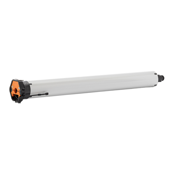
VariEco-868 roller shutter/awning drive
Keep these instructions in a safe place!
After installation of the tubular drive attach these instructions
to the cable for the electrician.
Device function:
• Commissioning the drive with the assembly cable
• Quick limit switch adjustment
When the drive is shipped from the factory, the quick limit
position adjustment is active.
Only use this function for the first adjustment.
The limit switches do not switch over during the quick limit
position adjustment process. Run to the limit positions. Carry
out the re-adjustment via the limit switch adjusting screws
after deactivation of the quick limit switch adjustment.
Further limit position changes are only possible via the limit
switch adjusting screw.
Important safety instructions!
Observe the following instructions.
Risk of injury due to electrocution.
The connections to the 230 V mains must be made by
Warning!
authorised specialist personnel.
Check the system (roller shutters, awnings) regularly
for wear or damage.
The regulations of the local energy supply company as
well as the regulations for wet and damp rooms
according to VDE 0100 must be followed when making
the connections.
Only use unmodified original elero electrical parts.
Keep people away from the system until it is stationary.
When working on the system (servicing, cleaning
windows etc.), always disconnect it from the mains
supply.
Intended use
• Please ensure that the radio installations are not operated in
areas of increased possible interference.
(e.g. hospitals, airports ...).
• The radio control is only permitted for devices and units with which
a functional interference in hand-held/wall-mounted transmitters
or receivers poses no danger for persons, animals or materials or
where this risk is covered by other safety appliances.
• The operator has no protection whatsoever from interferences
by other radio emitters and local terminals (e.g. also from radio
installations), that are normally used on the same frequency
range.
• Only use radio receivers with equipment and units approved by
the manufacturer.
Optimal use of the radio signal
• Do not bend the antenna.
• Do not shorten or extend the antenna.
• If reception is poor, adjust the antenna.
• Install the antenna so that it is as exposed as possible.
• The minimum distance between two radio drives must be at
least 15 cm.
Check the following before installation:
• Only turn the limit switch ring slightly before and during
assembly. (It interferes with the result of the end position
adjustment)
• The drive is only capable of operation as installed.
• Only perform connecting work with the power turned off.
• Do not connect motor plug with mains on.
• The hanging must be attached to the winding shaft.
• Do not drill in the area of the tubular motor!
• The profile tube must have sufficient clearance from the motor
tube.
Installation
Observe the following installation instructions!
– The drive must be fixed in such a way that it does
not endanger personnel.
Warning!
– Before installing the drive, all lines and equipment,
which are not required for operation, must be
removed from the site.
– During installation, during operation and when
work is carried out on the system, the option to
separate all three poles from the mains must
always exist (Hirschmann connector and
Hirschmann coupling or a two-pole switch with
minimum 3 mm contact gap or all-pole main
switch).
– If the drive is controlled by a switch with OFF pre-
setting (dead man's button), the momentary
contact switch must be fitted at a height of more
than 1.50 m and separated from the moving parts.
The travel range of the systems must always be
visible during operation.
– Moving parts in a drive, which are below 2.5 m,
must be protected.
– Set torque and set operating time must be
adapted to the requirements of the product which
is driven.
– Please note the technical data on the type plate.
– Please note that with this drive (type M and L
tubular motors) the smallest internal tube
diameter corresponds with 46 mm and 56 mm.
– The drive must be installed so that it cannot get
wet.
– Do not install drives in surroundings which are
at risk of explosion or in mobile appliances
(e.g. motor vehicles).
– Keep children away from the (remote) control unit.
Remove of the motor cable plug
Risk of injury due to
electric shock.
When the motor cable plug is
Warning!
removed the supply line must
have no voltage.
Delivery condition
Remove plug
2
Remove the motor cable plug
Switch off voltage supply.
1. Press locking mechanism on the plug towards the cable using a
screwdriver.
2. Pull out the plug.
Insert the motor cable plug
3. Switch off voltage supply. Insert plug until locking mechanism
engages.
Insert plug
1
3
Advertisement
Table of Contents

Related Manuals for elero VariEco-868


Summary of Contents for elero VariEco-868
- Page 1 Only use unmodified original elero electrical parts. – Please note the technical data on the type plate. Keep people away from the system until it is stationary. When working on the system (servicing, cleaning –...
- Page 2 UP button Mains UP button STOP button Auto STOP button Blue (neutral wire) DOWN Black Brown button DOWN Green-yellow button Back of wall transmitter elero LR03 (AAA) Programming button P 2. Switch on mains. Programming button P (Back of unit)
- Page 3 Mounting and initial operation Delivery status/factory setting Only at commissioning The quick limit switch Quick limit switch adjustment adjustment is activated at 1. Attach the hangings to the shaft. the factory. Quick limit switch Run in the DOWN direction if it is necessary to move the adjustment Releasing screw is in the winding shaft.
- Page 4 Adjustment of the end positions Setting of the upper end position Setting the lower end position (Fine adjustment or end position changes) (Fine adjustment or end position changes) 1. Allow the drive to run fully in the "Down" direction. 1. Press the DOWN button on the assembly cable and keep it depressed.
- Page 5 1. Switch off/on mains When the mains has been switched off for a short time, the drive is ready to be programmed for 5 minutes. LR03 (AAA) Auto elero LR03 (AAA) min. 3 sec. elero Programmed transmitter 2. Press simultaneously: UP and DOWN buttons and programming button P on the programmed transmitter for min.
- Page 6 Notes on troubleshooting Troubleshooting Fault Possible cause Remedy • Radio programming mode • Faulty connection • Check connection does not start • Drive not connected to mains • Check mains voltage • Time frame already expired (5 min) • Interrupt mains voltage briefly •...
- Page 8 NRG Automation Ltd. Tel. (44) 87 02 40 42 19 elero GmbH Linsenhofer Straße 59–63 info@elero.de Foundry Lane – Halebank Fax (44) 87 02 40 40 86 Antriebstechnik D-72660 Beuren www.elero.com Technical parameters subject to change Widnes, Cheshire WA8 8TZ sales@nrgautomation.co.uk...
Need help?
Do you have a question about the VariEco-868 and is the answer not in the manual?
Questions and answers