Table of Contents
Advertisement
Quick Links
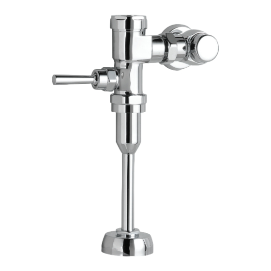
PINTBROOK URINAL
6002 SERIES
Thank you for selecting American Standard – the benchmark of fine quality for over 100 years. To ensure this product is
installed properly, please read these instructions carefully before you begin. (Certain installations may require professional
help.) Also be sure your installation conforms to local codes.
BEFORE YOU BEGIN
!
CAUTION: PRODUCT IS FRAGILE. TO AVOID BREAKAGE AND POSSIBLE INJURY HANDLE WITH CARE!
NOTES:
• Pictures may not exactly define contour of china and components.
• Observe all local plumbing and building codes.
• Refer to local codes and manufacturer's instructions for flush valve requirements.
• Carefully inspect the new urinal for damage.
• Fixture dimensions are nominal and conform to tolerances by ASME Standard A112.19.2.
• Site preparation may require additional tools and hardware.
Recommended Tools AND MATERIALS
Safety Glasses
Tape Measure
Thread Sealant
1/4" Ratchet
Top Spud
P r o d u c t n a m e s l i s t e d h e r e i n a r e t r a d e m a r k s o f A S A m e r i c a I n c .
© A S A m e r i c a I n c . 2 0 1 6
Adjustable Wrench
Hole Cutting Equipment
FINISHED
64mm
WALL
(2-1/2")
419mm
(16-1/2")
366mm
(14-7/16")
13mm
(1/2")
FINISHED
FLOOR
2" N.P.T.
FEMALE
OUTLET
CONNECTION
Blade Screwdriver
MANUAL
OVERRIDE
15
BUTTON
292mm
(11-1/2")
326mm
(12-13/16")
364mm
140mm
(14-5/16")
(5-1/2")
C/L OF
OUTLET
432mm (17")
MAXIMUM
610mm (24")
OPTIONAL
TO FINISHED
FLOOR
GASKET
102mm
(4")
2" N.P.T.
INSIDE THREADS
DETAIL OF OUTLET CONNECTION
Pencil
Levels
108mm to 133mm
(4-1/4" to 5-1/4")
SUPPLY
DN 20mm
(3/4" I.P.S.)
WALL HANGERS
(INCLUDED)
575mm
(22-5/8")
334mm
(13-1/8")
102mm
(4")
10mm
(3/8")
16mm
(5/8")
FINISHED WALL
7302219-100 Rev. A 6/ 16
Advertisement
Table of Contents

Subscribe to Our Youtube Channel
Related Manuals for American Standard 6002 Series


Summary of Contents for American Standard 6002 Series
- Page 1 PINTBROOK URINAL 6002 SERIES Thank you for selecting American Standard – the benchmark of fine quality for over 100 years. To ensure this product is installed properly, please read these instructions carefully before you begin. (Certain installations may require professional help.) Also be sure your installation conforms to local codes.
- Page 2 In Canada: In Mexico: In the United States: American Standard Brands AS Canada, ULC American Standard B&K Mexico 5900 Avebury Rd. S. de R.L. de C.V. P.O. Box 6820 Mississauga, Ontario Via Morelos #330...
- Page 3 M965020 Rev.2.1 (5/19) NOTE TO INSTALLER: Please give this manual to the customer after installation. NOTE TO INSTALLER: Please give this manual to the customer after installation. To learn more about American Standard Selectronic ® Products visit our website at: www.americanstandard-us.com or e-mail us at: CRTTEAM@lixilamericas.com...
- Page 4 Thank you for selecting American-Standard...the benchmark of fine quality for over 100 years. To ensure that your installation proceeds smoothly--please read these instructions carefully before you begin. All American Standard Products Are Water Tested At Our Factory. UNPACKING Some Residual Water May Remain In The Valve During Shipping.
- Page 5 Fig. 1 GENERAL DESCRIPTION: Roughing-in Dimensions FINISHED WALL MANUAL FLUSH VALVE, .125 GPF 38mm-127mm 108mm-133mm Exposed Flushometer (1-1/2-5") (4-1/4" to 5-1/4") for 3/4" Top Spud Fixtures Exclusive, self cleaning piston-operated flush valve. OPERATING PRESSURE: Overall Range: 20-125 psi ** SUPPLY DN 19mm Recommended: 20 psi (flowing)- (3/4"...
- Page 6 INSTALL SWEAT SOLDER Fig.3 Fig.3a ADAPTER; Fig. 3 FINISHED WALL CENTER LINE OF Turn water supplies off CAUTION FIXTURE SPUD before beginning Note: Install Optional Sweat Solder Adapter (Supplied) for copper pipe supply line. Fig. 3. (A-B)= 1. Measure the distance (A) from the finished wall to the 32mm center of the inlet spud on the fixture.
- Page 7 INSTALL FLUSH VALVE; Fig. 6a Fig. 6a & 6b 1. As shown in Fig. 6a, insert the side INLET FLANGE (1) on the FLUSH VALVE (2) into the SUPPLY STOP (3). Lubricate the INLET FLANGE O-RING (4) with water if necessary.
- Page 8 If these items do need replacement they must be purchased separately or order the complete flush valve assembly from American Standard. 1. Remove COVER (1) from SUPPLY STOP (2) if installed. Fig. 9.
Need help?
Do you have a question about the 6002 Series and is the answer not in the manual?
Questions and answers