
Subscribe to Our Youtube Channel
Related Manuals for schmersal RSS 36-I1-D-ST


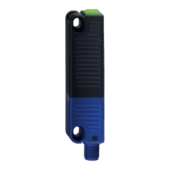
Summary of Contents for schmersal RSS 36-I1-D-ST
-
Page 1: Table Of Contents
INSTRUCTIONS FOR OPERATION AND ASSEMBLY Electronic safety-sensor RSS 36-I1-D-ST Table of Contents 1 About this document 1.1 Function 1.2 Target group of the operating instructions: authorised qualified personnel 1.3 Explanation of the symbols used 1.4 Appropriate use 1.5 General safety instructions 2 Product description 2.1 Ordering code... -
Page 2: Function
The Schmersal range of products is not intended for private consumers. 1.1 Function This document provides all the information you need for the mounting, set-up and commissioning to ensure the safe operation and disassembly of the switchgear. The operating instructions enclosed with the device must always be kept in a legible condition and accessible. -
Page 3: General Safety Instructions
The user must observe the safety instructions in this operating instructions manual, the country specific installation standards as well as all prevailing safety regulations and accident prevention rules. Further technical information can be found in the Schmersal catalogues or in the online catalogue on the Internet: products.schmersal.com. -
Page 4: Purpose
For special versions, which are not listed in the ordering code, these specifications apply accordingly, provided that they correspond to the standard version. 2.3 Purpose This non-contact, electronic safety sensor is designed for application in safety circuits and is used for monitoring the position of movable safety guards. -
Page 5: Technical Data
unauthorised spare parts or accessories. For safety reasons, invasive work on the device as well as arbitrary repairs, conversions and modifications to the device are strictly forbidden, the manufacturer shall accept no liability for damages resulting from such invasive work, arbitrary repairs, conversions and/or modifications to the device. - Page 6 Diagnostic output Short circuit detection Cross-circuit detection Series-wiring Safety functions Cascadable Integral system diagnostics, status Number of LEDs Number of semi-conductor outputs with signaling function Number of fail-safe digital outputs Safety classification Standards EN ISO 13849-1 EN IEC 61508 Performance Level, up to Category PFH value 2.70 x 10⁻¹⁰...
- Page 7 Type of the fixing screws 2x M4 (cylinder head screws with washers DIN 125A / form A) Tightening torque of the fixing screws, minimum 2.2 Nm Tightening torque of the fixing screws, maximum 2.5 Nm Mechanical data - Switching distances according EN IEC 60947-5-3 Switch distance, typical 12 mm Assured switching distance "ON"...
- Page 8 Ambient conditions - Insulation values Rated insulation voltage U 32 VDC Rated impulse withstand voltage U 0.8 kV Overvoltage category Degree of pollution Electrical data Operating voltage 24 VDC -15 % / +10 % (stabilised PELV power supply) Operating current, minimum 0.5 mA No-load supply current I , maximum...
- Page 9 Voltage, Utilisation category DC-13 24 VDC Current, Utilisation category DC-13 0.25 A Test pulse interval, typical 1000 ms Test pulse duration, maximum 0.3 ms Classification ZVEI CB24I, Source Classification ZVEI CB24I, Sink Electrical data - Diagnostic outputs Designation, Diagnostic outputs Design of control elements short-circuit proof, p-type Voltage drop U...
-
Page 10: Mounting
This device complies with the nerve stimulation limits (ISED CNR-102) when operated at a minimum distance of 100 In the event of changes or modifications that have not been expressly approved by K.A. Schmersal GmbH & Co. KG, the user's authorisation to use the device may become ineffective. -
Page 11: Dimensions
To avoid any interference inherent to this kind of system and any reduction of the switching distances, please observe the following guidelines: The presence of metal chips in the vicinity of the sensor is liable to modify the switching distance. Keep away from metal chips Minimum distance 100 mm between two safety sensors as well as other systems with same frequency (125 kHz) The actuator must be permanently fitted to the safety guards and protected against displacement by suitable measures... -
Page 12: Accessories
Alternative suitable actuators with different design: refer to products.schmersal.com. 4.3 Accessories Set of disposable screws (order separately) - 4x M4x25 incl. washers, order number 101217746 - 4x M4x30 incl. washers, Bestellnummer 101217747 Sealing kit (order separately) - Order number 101215048 - 8 plugs and 4 under seals - To seal the mounting holes and as a spacer (approx. -
Page 13: Switch Distance
4.4 Switch distance Switching distances in mm to IEC 60947-5-3 Typical switching distance s Assured switching distance s Assured switch-off distance s There are new switch distances as per the table below owing to the necessity of technical modifications (V2). Please check the design of your guard system following installation to ensure adherence to the secured switch distances (≤... -
Page 14: Adjustment
With the combination of "old sensor - new actuator (V2)" there may be limitations in availability owing to the reduced s mm). This change has no affect on the performance level. The side allows for a maximum height misalignment (X) of sensor and actuator of ± 8 mm (e.g. mounting tolerance or due to guard door sagging). -
Page 15: Electrical Connection
Requirements for the connected safety-monitoring module: dual-channel safety input, suitable for p-type sensors with NO function Information for the selection of suitable safety-monitoring modules can be found in the Schmersal catalogues or in the online catalogue on the Internet: products.schmersal.com. -
Page 16: Wiring Examples For Series-Wiring
For convenient wiring and series-wiring of SD components, the SD junction boxes PFB-SD-4M12-SD (variant for the field) and PDM-SD-4CC-SD (variant for control cabinet on carrier rail) are available along with additional comprehensive accessories. Detailed information is available on the Internet, products.schmersal.com. 5.3 Wiring examples for series-wiring Series-wiring can be set up. -
Page 17: Wiring Configuration And Connector Accessories
Y1 and Y2 = Safety outputs → Safety monitoring module SD-IN → Gateway → Field bus 5.4 Wiring configuration and connector accessories Function safety switchgear Pin configuration of the Colour codes of the Schmersal Poss. connector connectors colour codes of... -
Page 18: Actuator Coding
Connecting cables with coupling (female) IP67 / IP69, M12, 8-pole - 8 x 0.25 mm² to DIN 47100 Cable length Ordering code 2,5 m 103011415 5,0 m 103007358 10,0 m 103007359 15,0 m 103011414 Connecting cables with coupling (female) IP69K, M12, 8-pole - 8 x 0,21 mm² Cable length Ordering code 5,0 m... -
Page 19: Working Principle And Diagnostic Function
7 Working principle and diagnostic function 7.1 Mode of operation of the safety outputs The safety outputs can be integrated into the safety circuit of the control system. The opening of a safety guard, i.e. the actuator is removed out of the active zone of the sensor, will immediately disable the safety outputs of the sensor. - Page 20 Error Errors which no longer guarantee the function of the safety switchgear (internal errors) cause the safety outputs to be disabled within the duration of risk. After fault rectification, the error message is reset by opening and re-closing the corresponding safety guard. Error warning A fault that does not immediately endanger the safety function of the safety switchgear (e.g.
-
Page 21: Safety-Sensors With Serial Diagnostic Function
Table 1: Examples of the diagnostic function of the safety-sensor with conventional diagnostic output Sensor function LED's Diagnostic- Safety Comments output outputs green yellow Y1, Y2 Supply voltage Voltage on, no evaluation of the voltage quality actuated 24 V 24 V The yellow LED always signals... - Page 22 Gateway is integrated as a slave in an existing field bus system. In this way, the diagnostic signals can be evaluated by means of a PLC. The necessary software for the integration of the SD-Gateway is available for download at products.schmersal.com. The response data and the diagnostic data are automatically and permanently written in the assigned input byte of the PLC for each safety sensor in the series-wired chain.
- Page 23 Table 2: Function of the visual diagnostic LEDs, the serial status signals and the safety outputs by means of an example System LED's Safety Status signals serial diagnostic byte Bit n° conditio outputs green yellow Y1, Y2 Non- actauted , inputs X1 and enabled Actuated...
-
Page 24: Set-Up And Maintenance
Table 3: Tabular overview of status signals, warnings or error messages(The described condition is reached, when Bit = 1) Communication directions: Request byte: from the PLC to the local safety sensor Response byte: from the local safety sensor to the PLC ... -
Page 25: Disassembly And Disposal
£ legislations. 25-25 Schmersal, Inc., 15 Skyline Drive, Hawthorne, NY 10532 The details and data referred to have been carefully checked. Images may diverge from original. Further technical data can be found in the manual. Technical amendments and errors possible.
Need help?
Do you have a question about the RSS 36-I1-D-ST and is the answer not in the manual?
Questions and answers