Table of Contents
Advertisement
Quick Links
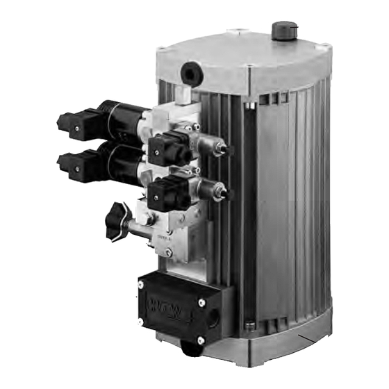
Compact hydraulic power packs type KA and KAW
for short-term and intermittent service
for 3
and 1
phase power supply, as single or dual circuit pumps
+
+
Flow Q
= 19.9 lpm (1450 rpm)
max
Operating pressure p
= 700 bar
max
1.
Design and general information
1.1
Basic design
The compact hydraulic power pack type KA serves to
supply pressurized fluid for intermittently or short-term
operated hydraulic circuits.
The basic hydraulic power pack consists:
o the tank (available in different sizes)
o the drive motor (available for different voltages and power
requirements)
o the radial piston or gear pump directly driven by the
motor shaft
The compact style obtained with this design represents an
essential
advantage
Complete turn-key solutions can be easily arranged via a
wide range of connection blocks (see D 6905 ++) and
directly mountable valve banks (see photo).
There is a wide field of applications for theses compact
power packs within tool machines, jig assemblies and
general mechanical engineering.
The power pack is suited for operation modes S2 (short
time service) and S3 (intermittent service). The load can be
up to 1.8 of the nom. power rating during these operation
modes.
Table of contents
1.
General information ......................................1
1.1
Basic design ..................................................................... 1
2.
Available versions ......................................... 2
2.1
Motor and tank section .................................................... 2
2.2
Pump section.................................................................... 4
2.2.1
Single circuit pumps ......................................................... 4
2.2.2
Dual circuit pumps ........................................................10
3.
Additional parameters .................................11
3.1
General .............................................................................11
3.2
Hydraulic ........................................................................... 12
3.3
Electrical .......................................................................... 12
© 2006 by HAWE Hydraulik
opposite
conventional
units.
HAWE HyDrAuliK SE
STREITFELDSTR. 25 • 81673 MÜNCHEN
Additional information:
Compact hydraulic power packs type KA 4 D 8010-4
>
=
;
Tank with pressed in stator
<
Fluid filling / breather
=
Terminal box or alternatively: Version with plug Co. HARTING
>
Connection pedestal with one (single circuit pump) or two
pressure ports (dual circuit pump) and one return port.
Prepared for the mounting of connection blocks for ongoing
pressure and reflow pipes or with directly mounted directional
valve banks (see D 6905 ++).
Order example
KA 24 ST/H 0,66
- A 2/650
- VB 11 FM-H 3 N 3-1-N 24-
3x400 V 50 Hz
4.
Dimensions .................................................. 16
4.1
Mounting hole pattern ...................................................... 16
4.2
Basic pump ....................................................................... 17
4.3
Electrical and hydraulic connections ................................ 20
5.
Appendix ...................................................... 22
5.1
Notes regarding selection................................................ 22
5.2
Assembly and installation notes ........................................ 26
5.3
Servicing ........................................................................... 28
5.4
Declaration of conformity ................................................. 28
type HC
D 7900
type HCG D 7900 G
type NPC D 7940
type MPN D 7207
type HK
D 7600 ++
<
;
D 8010
Compact power pad
KA and KAW
December 2011-00
1.
1
Advertisement
Table of Contents

Related Manuals for HAWE Hydraulik KA


Summary of Contents for HAWE Hydraulik KA
-
Page 1: Table Of Contents
Flow Q = 19.9 lpm (1450 rpm) Additional information: Operating pressure p = 700 bar Compact hydraulic power packs type KA 4 D 8010-4 type HC D 7900 type HCG D 7900 G type NPC D 7940 type MPN D 7207... -
Page 2: Available Versions
D 8010 page 2 Available versions, type coding Motor and tank section Order examples: KA 24 1 S KS E/H1,81 - A 1/280 - 3x400V 50 Hz KA 28 22 L1 KTF P/HZ 0,59/8,8-... 3x400V 50 Hz/24V DC - G 1/2 x 300... - Page 3 M12x1 on right or left side for temperature and/or float E, PE Electrical connection with additional interference suppression in the terminal box or at the plug Co. HARTING. For alternatives, see sect. 3.3, only with type KA Table 1f: Fluid drain hose Coding...
-
Page 4: Pump Section
D 8010 page 4 Pump section 2.2.1 Single circuit pumps - H6,7 - Order example 1: KA 242 DT/1 A1/180 3 x 400V 50Hz - Z4,5 Order example 2: KAW 26/1P1 - AL11E/120 3 x 400/230V 50Hz Table 2a: Single circuit pumps with 3+phase motor... - Page 5 Delivery flow coding 1,84 2,66 3,12 3,61 3,69 4,14 Geom. displace V /rev) 1.41 2.04 2.39 2.77 2.83 3.18 KA 21 Perm. pressure p (bar) Delivery Q (lpm) 50 Hz 3.90 5.65 6.62 7.67 7.84 8.81 4.69 6.79 7.96 9.22 9.42...
- Page 6 Coding for gear Size 1 Z 1,1 Z 1,7 Z 2,0 Z 2,7 Z 3,5 Z 4,5 Delivery flow coding Geom. displace V /rev) KA 21 Perm. pressure p (bar) Delivery Q (lpm) 50 Hz 2.23 3.07 3.91 5.30 6.70 60 Hz 2.68...
- Page 7 D 8010 page 7 Table 2b: Single circuit pumps with 1+phase motor radial piston pump H or gear pump Z Note: The delivery flow rating Q is a guide line figure, based on nom. rev. rating that will be slightly reduced dep. on load (see curves in sect.
- Page 8 D 8010 page 8 Continuation of table 2b: Note: o Version with pump elements type PE acc. to D 5600 o Only available as vertical version (see table 1c) Coding for radial piston pump Piston diameter (mm) Number of pump elements Delivery flow coding 1,84 2,66...
- Page 9 D 8010 page 9 Continuation of table 2b: Coding for gear Size 1 Z 1,1 Z 1,7 Z 2,0 Z 2,7 Z 3,5 Z 4,5 Delivery flow coding Geom. displace V /rev) KAW 21 Perm. pressure p (bar) Delivery Q (lpm) 50 Hz 2.23...
-
Page 10: Dual Circuit Pumps
D 8010 page 10 2.2.2 Dual circuit pump with joint connection pedestal a) Version radial piston pump -- radial piston pump HH and radial piston pump -- gear pump coding HZ Order example 1: KAW 24 1 S KS E / H H 0,34 / 2,0 - NA31 - ... 1 + 230V 50 Hz Order example 2: 24 11 S KS E / H Z 0,34 / 6,9 - NA31 - ... -
Page 11: Additional Parameters
Gear pump Z 1,1 ... Z 6,9: 700 ... 4000 rpm Z 8,8 ... Z 11,3: 500 ... 1800 rpm Installed position Vertically (KA...S) or horizontally (KA...L) Observe notes regarding horizontal version, see sect. 4.2 Mounting Tapped holed M8, see dimensional drawings Mass (weight) H (3 cyl.) -
Page 12: Hydraulic
D 8010 page 12 Hydraulic Pressure Delivery side (outlet ports P) depending on pump design and delivery flow, see sect. 2.2 Suction side (inside the tank): ambient pressure. Not suitable for charging. Starting against pressure Versions with 3+phase motor will start-up against pressure p ! Whereas versions with 1+phase motor will start-up only against slight pressure! Pressure fluid... - Page 13 (pV (V), f (Hz) (kW) (rpm) cos j (µF) (bar cm KA 21 3x400/230V 50 Hz !/ 0.55 2790 1.25/2.2 0.84 3x460/265V 60 Hz !/ 0.66 3350 1.3/2.25 0.88 3x690V 50 Hz ! 0.55 2790 0.73...
- Page 14 D 8010 page 14 Current consumption KA 23 KA 24 KA 28 Oper. voltage 3 x 400/230V 50 Hz !/ 3 x 460/265V 60 Hz !/ Hydraulic work (pV ) (bar cm KA 21 KA 22 KA 26 Oper. voltage...
- Page 15 D 8010 page 15 KAW 23 KAW 24 KAW 28 Oper. voltage 1 x 230V 50 Hz 1 x 110V 60 Hz Hydraulic work (pV ) (bar cm KAW 21 KAW 22 KAW 26 Oper. voltage 1 x 230V 50 Hz 1 x 110V 60 Hz Hydraulic work (pV ) (bar cm...
-
Page 16: Dimensions
D 8010 page 16 Aux. blower Motor data Coding F, F1 (W) Revolutions Protection class (rpm) 1x230V 50/ 60 Hz ( 2800/ 3250 IP 44 1x110V 60 Hz ( 3250 IP 44 24V DC 3050 IP 20 Temperature range -30°C ... +50°C Electrical connection Plug conf. -
Page 17: Basic Pump
D 8010 page 17 Basic pump Vertical version Tank size Coding 1 Tank size without coding Suppressor Coding E ) There is an additional fluid gauge in the tank extension with tank size coding 1, 2, 11, 21, 3 and optional fluid gauge coding K, KS, KD. - Page 18 D 8010 page 18 Horizontal version Tank size without coding Terminal box (coding P see page 19) Example: Connection block A1/... Tank size Tank size Coding 1 Coding 01, 11, 02, 22 Note: In case a version intended for horizontal use is installed Tank size vertically the breather has to be positioned on top and the Coding 2, 3...
- Page 19 D 8010 page 19 Options Terminal box Coding P Suppressor Coding PE Aux. blower Coding F, F1 Horizontal version Vertical version Electr. connection Min distance aux. blower Min distance Silica gel filter Coding G Fluid drain hose Coding G 1/2 x 300 Coding G 1/2 W x 300 G 1/2 x 500...
-
Page 20: Electrical And Hydraulic Connections
D 8010 page 20 Electrical and hydraulic connections Hydraulical Single circuit pump Centering pin (sect. 2.2.1) 2xM8, 13 deep Centering pin 2xM6, 13 deep Hole dimensions for customer furnished connection block Dual circuit pump with joint connection pedestal (sect. 2.2.2) For missing dimensions, see above ! Port sealing:... - Page 21 D 8010 page 21 Coding P Plug Co. HARTING HAN 10 E 3+phase motor 1+phase motor Electr. connection feed-in side (plug) 3+phase motor ! 3+phase motor / 1+phase motor - operating capacitor (not scope of delivery) Coding D, S Coding T Coding DT, ST D (NC-contact) S (NO-contact)
-
Page 22: Appendix
- S6 – Permanent operation with intermittent load (only suited when combined with auxiliary blower coding F) e) Selection of a hydraulic power pack o Selection of the basic type based on the power supply - 3+phase mains type KA - 1+phase mains type KAW Motor selection... - Page 23 D 8010 page 23 f) Calculation of the hydraulic work o Calculation of the middled pressure o Calculation of the middled hydraulic work (middled oper. pressure x delivery flow) o Calculation of the max. hydraulic work (max. oper. pressure x delivery flow) (bar) = calculated, middled pressure per cycle during while load is applied t + ...
- Page 24 D 8010 page 24 h) Determining the max. current consumption see curves in sect. 3.3 For setting of the motor protective switch, see sect. 5.2 c i) Selection of the proper operation capacitor with type KAW A capacitor is mandatory for the version with 1+phase motor. The recommendations in sect. 3.3 table 9 ensure that the max. pressure rating specified are achieved.
- Page 25 D 8010 page 25 l) Selection of a connection block A connection block is mandatory for the hydraulic connection of the hydraulic power pack. Type Description Pamphlet A, AL, AM, AK, For single circuit pumps D 6905 A/1 AS, AV, AP with pressure limiting valve and the possibility for direct mounting of directional valve banks Optional:...
-
Page 26: Assembly And Installation Notes
ON/OFF. This effect can be minimized by means of a filter e.g. type 23140, 3x400V AC 4kW 50-60 Hz (Co. MURR-ELEKRONIK, D-71570 Oppenweiler) There is an optional suppressor (Coding E or PE, see sect. 2.1, table 1e) available for type KA, which can be directly mounted either at the terminal box or at the plug Co. HARTING... - Page 27 D 8010 page 27 e) Putting into operation o Check, whether the compact hydraulic power pack is professionally connected. - Electrically: Power supply, controls - Hydraulically: Piping, hoses, cylinders, motors - Mechanically: Fastening at the machine, the frame, and the rack o A protective motor switch should be employed to safeguard the electric motor.
-
Page 28: Servicing
D 8010 page 28 Servicing The hydraulic power packs type MP and the valves being directly mounted onto the hydraulic power pack are almost maintenance free. Only the fluid level should be checked regularly depending on operation conditions. The fluid should be replaced every year as a general rule, but more frequently if tests show aging or contamination, filters (pressure or return) have to be replaced accordingly.
Need help?
Do you have a question about the KA and is the answer not in the manual?
Questions and answers