
Related Manuals for HAWE Hydraulik A 100


Summary of Contents for HAWE Hydraulik A 100
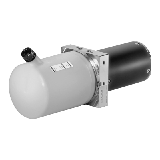
- Page 1 Mini hydraulic power pack type A 100 and A Original assembly instructions Operating pressure p 210 bar Usable volume V 0.2 to 0.8 l B 6025 12-2021 -1.1 en...
- Page 2 HAWE Hydraulik respects these legal provisions in all cases. HAWE Hydraulik cannot provide individual guarantees that the stated circuits or procedures (including in part) are not subject to the intellectual property rights of third parties.
-
Page 3: Table Of Contents
Checking the hydraulic uid level and replacing it....................23 8.2.4 Replacing 2/2-directional seated valve SP3......................24 Disassembly and disposal..........................25 Troubleshooting..............................26 Appendix................................27 11.1 Technical data..............................27 11.1.1 Operating conditions............................27 11.1.2 Weights and measures............................28 11.1.3 Electrical data..............................28 11.2 Circuit diagram..............................33 HAWE Hydraulik SE B 6025 - 12-2021 - 1.1en 3/34... -
Page 4: About These Instructions
Information to ensure the correct use of the product. Safety symbols General safety symbol Draws your attention to additional safety information. Slipping hazard Dragging hazard from moving parts Harmful substances Tripping and falling hazard 4/34 B 6025 - 12-2021 - 1.1en HAWE Hydraulik SE... -
Page 5: Applicable Documents
DIN 51524 Pressure uids - Hydraulic oils - Part 1: HL hydraulic oils, Minimum requirements ISO 4406 D 6025 Mini hydraulic power pack type A 100 and A 065 data sheet HAWE Hydraulik SE B 6025 - 12-2021 - 1.1en 5/34... -
Page 6: For Your Safety
Avoid re, open ames and smoking in the vicinity of the product. Immediately dispose of combustible materials wetted with hydraulic uid as special waste. Do not use ammable or corrosive cleaning uids. 6/34 B 6025 - 12-2021 - 1.1en HAWE Hydraulik SE... -
Page 7: Duties Of The Operator
Ensure the terms of the industrial safety and operating instructions are observed. Only use qualied personnel. Due to their training and experience, the qualied personnel must be able to recognize risks and avoid possible hazards. HAWE Hydraulik SE B 6025 - 12-2021 - 1.1en 7/34... -
Page 8: Qualification Of The Personnel
Personal protective equipment is designed to prevent and reduce hazards. In the instructions, safety instructions with mandatory symbols indicate the wearing of special protective equipment for special activities. Instruction and supply is carried out by the operator. 8/34 B 6025 - 12-2021 - 1.1en HAWE Hydraulik SE... -
Page 9: About This Product
The type plate can be found on the equipment rack with the following information: Material number (6XX-XXXX-X) ■ Serial number ■ Production date (week, year) ■ (2) Hydraulic uid inlet (oil) (3) Engravings for hydraulic connections (P / T) HAWE Hydraulik SE B 6025 - 12-2021 - 1.1en 9/34... -
Page 10: Structure
A 065 Hydraulic uid ller plug (M 14x1.5) Tank Equipment rack with pump and pressure-limiting valve Motor A 100 H Hydraulic uid ller plug (M 14x1.5) Tank Equipment rack with • pump • pressure limiter P3B •... -
Page 11: Functions
A 100 Q Hydraulic uid ller plug (M14 x 1.5) Tank Equipment rack with • pump • check and pressure-limiting valve Motor The external gear pump is directly ange-mounted via specic equipment rack/Q or H on the motor. The condition and quality of the hydraulic uid can be easily checked via the plastic cover on the hydraulic tank. -
Page 12: Control
The pressure-limiting valve (P3B) is factory-set and safeguards the hydraulic system against excessive ■ pressure. The motor’s duty cycle should be monitored by the device control. An increase in the duty cycle is an ■ indicator of abnormal internal leakage. 12/34 B 6025 - 12-2021 - 1.1en HAWE Hydraulik SE... -
Page 13: Transport And Storage
(connections P and T sealed with plastic screw plugs). ■ Scope of delivery does not include: bolts, screws and sleeves for attachment ■ electrical connecting lines (if to be attached separately on the motor) ■ hydraulic uid ■ HAWE Hydraulik SE B 6025 - 12-2021 - 1.1en 13/34... -
Page 14: Checking The Delivery
Protect the valves and valve controllers against gumming of the hydraulic uid if stored more than 2 ■ years. To do so, contact the manufacturer of the hydraulic uid. Avoid mechanical jolts. ■ 14/34 B 6025 - 12-2021 - 1.1en HAWE Hydraulik SE... -
Page 15: Assembly And Installation
Property damage from incorrectly installed hydraulic system Assembly by trained specialists only. Ensure all labels and markings of the hydraulic system are easily visible and legible after assembly. Check installation space/connection points for damage. HAWE Hydraulik SE B 6025 - 12-2021 - 1.1en 15/34... -
Page 16: Electrical Connection
People with pacemakers or implanted defibrillators must maintain a sufcient distance from magnets. Advise people with pacemakers or implanted defibrillators against approaching magnets. Cordon off the area around the drive system and afx suitable warning signs to the barriers. 16/34 B 6025 - 12-2021 - 1.1en HAWE Hydraulik SE... - Page 17 5. Connect the hydraulic power pack to the electrical power supply. 6. Check the electrical connection after a week’s operating time. When connecting the temperature sensor and motor, observe the pin assignment from the applicable technical data sheet (D 6025). HAWE Hydraulik SE B 6025 - 12-2021 - 1.1en 17/34...
-
Page 18: Start-Up
5. Check the hydraulic uid level again after several strokes or after the hydraulic system has been vented. 6. Check the valve switching and function sequence. 7. After a week of operating time at the latest, check the ttings. 18/34 B 6025 - 12-2021 - 1.1en HAWE Hydraulik SE... -
Page 19: Operation
The product is switched on and off via the system control in accordance with the machine manufacturer’s operating instructions. For this, the commissioning of the product must have been performed properly. HAWE Hydraulik SE B 6025 - 12-2021 - 1.1en 19/34... -
Page 20: Maintenance
Omitted or negligently performed maintenance can cause the hydraulic system to malfunction. Improperly performed maintenance or improperly conducted troubleshooting can pose a danger to personnel. Read and abide by all instructions provided in this section. 20/34 B 6025 - 12-2021 - 1.1en HAWE Hydraulik SE... - Page 21 Use suitable aids when lling or bleeding. Check all connecting elements that convey oil for leaks before switching on the motor in the parent system. Wipe up leaked hydraulic uid with suitable aids. HAWE Hydraulik SE B 6025 - 12-2021 - 1.1en 21/34...
-
Page 22: Maintenance Plan
After 5 minutes, check the leak again to see if hydraulic uid has escaped. If hydraulic uid has escaped again, re-tighten the hydraulic connections. If re-tightening the hydraulic connections does not prevent hydraulic uid from escaping, the hydraulic power pack must be replaced. 22/34 B 6025 - 12-2021 - 1.1en HAWE Hydraulik SE... -
Page 23: Venting The Hydraulic System
(Recommended lter: 10 μm.) 8. Pour the ltered hydraulic uid into the tank using a funnel via the ller and breather lter. 9. Close the tank. 10.Attach the hydraulic power pack again. HAWE Hydraulik SE B 6025 - 12-2021 - 1.1en 23/34... -
Page 24: Replacing 2/2-Directional Seated Valve Sp3
6. Push in the new seated valve and screw on both cylinder screws M 6x12 with a tightening torque of 3+0.5 Nm. 7. Connect the connection cable to the coil of the solenoid valve. 8. Check the function of the solenoid valve by actuating. 9. Commission the hydraulic power pack. 24/34 B 6025 - 12-2021 - 1.1en HAWE Hydraulik SE... -
Page 25: Disassembly And Disposal
uid according to the regional waste disposal requirements. Dispose of the electronic components at approved collection points or with approved disposal companies according to local regulations. Dispose of metal with approved specialist disposal companies. HAWE Hydraulik SE B 6025 - 12-2021 - 1.1en 25/34... -
Page 26: Troubleshooting
Solenoid M faulty Replace 2/2-directional ∞, solenoid M faulty. seated valve SP3. Cylinder does not hold 2/2-directional seated Replace 2/2-directional position valve SP3 is not tight seated valve SP3. (For version H) 26/34 B 6025 - 12-2021 - 1.1en HAWE Hydraulik SE... -
Page 27: Appendix
Environment: approx. -15 to +80 °C, hydraulic uid: +10 to +40 °C A 100 Environment: approx. -30 to +80 °C, hydraulic uid: -15 to +80 °C Pay attention to the viscosity range Service life 10 years with max. 10,000 cycles HAWE Hydraulik SE B 6025 - 12-2021 - 1.1en 27/34... -
Page 28: Weights And Measures
Electrical connection 2 x ex (2x) Protection class IP50 per DIN 40050 Temperature measurement Motor Terminal assignment Rotation direction of the motor shaft: left (looking at the black shaft) black 28/34 B 6025 - 12-2021 - 1.1en HAWE Hydraulik SE... - Page 29 Sp operating pressure (bar); Q delivery ow (lpm); I current consumption (A) Motor A4D voltage 24 V (DC) Nominal power 100 W duty cycle up to 40 % (depends on je nach delivery ow, pressure, environmental condition) HAWE Hydraulik SE B 6025 - 12-2021 - 1.1en 29/34...
- Page 30 40 % (depends on je nach delivery ow, pressure, environmental condition) electrical connection 2 x eyelet AWG 16 (1000 mm) red +, black - protection class IP50 concerning to DIN 40050 Terminal assignment Rotation direction of the motor shaft: left (looking at the shaft) black 30/34 B 6025 - 12-2021 - 1.1en HAWE Hydraulik SE...
- Page 31 1 x M6 and 1 x M8 for eyelet, 1 x 6.3 x 0.8 for at push-in receptacle protection class IP54 concerning to DIN 40050 Terminal assignment Rotation direction of the motor shaft: left (looking at the shaft) M8 - red M6 - black HAWE Hydraulik SE B 6025 - 12-2021 - 1.1en 31/34...
- Page 32 40 % (depends on je nach delivery ow, pressure, environmental condition) electrical connection cables with ferrules protection class IP44 concerning to DIN 40050 Terminal assignment Rotation direction of the motor shaft: left (looking at the shaft) brown black blue yellow/green 32/34 B 6025 - 12-2021 - 1.1en HAWE Hydraulik SE...
-
Page 33: Circuit Diagram
Characteristic line pump A, Sp operating pressure (bar); Q delivery ow (lpm) 11.2 Circuit diagram Lifting version (H) One ow direction (Q) Contact details Headquarters Barbing HAWE Hydraulik SE HAWE Micro Fluid GmbH Einsteinring 17 Borsigstraße 11 85605 Aschheim 93092 Barbing Germany Germany e-mail: info@hawe.de... - Page 34 Further information HAWE Hydraulik SE is a responsible development partner with application expertise and experience in more than 70 areas of mechanical and plant engineering. The product range includes hydraulic power packs, constant and variable pumps, valves, sensors and accessories.
Need help?
Do you have a question about the A 100 and is the answer not in the manual?
Questions and answers