Advertisement
Quick Links
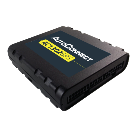
AC1302GPS
Wiring Diagram
White - Key Ignition Source (+)
Black - GND
Green - Starter Disable Out (-)
AC1302GPS
Red (12V+) - Constant
1. Connect Red wire to Constant +12V and fuse.
2. Connect Black wire to Ground.
3. Connect White wire to True Ignition (+).
4. Connect Violet wires to either end of vehicle starter interrupt wire.
Fuse
Violet
Violet
Vehicle Start
Interrupt Wire
Fuse
QUICK
INSTALL GUIDE
AC1302GPS
MUST BE TESTED!
CALL TO TEST GPS TRACKING DEVICE BEFORE CLOSING UP THE DASH
FAILURE TO FOLLOW THESE INSTRUCTIONS MAY DAMAGE EQUIPMENT AND VOID ITS WARRANTY
1.855.287.4477
8AM - 5PM Monday to Friday MT
CERTIFIED TRACKING SOLUTIONS
12V
ONLY!
Advertisement

Summary of Contents for AutoConnect AC1302GPS
- Page 1 AC1302GPS QUICK INSTALL GUIDE AC1302GPS Wiring Diagram White - Key Ignition Source (+) Fuse Black - GND Violet Green - Starter Disable Out (-) AC1302GPS Violet Vehicle Start Interrupt Wire Red (12V+) - Constant Fuse ONLY! 1. Connect Red wire to Constant +12V and fuse.
- Page 2 AC1302GPS Select in-vehicle device location Connect starter disable An appropriate location would be just under the plastic "top skin" of the The device prevents the vehicle from starting by triggering a relay to open dash, just above/behind the cluster and disconnect a "Vehicle Start Interrupt Wire". Starter disable is optional, please check with your supervisor before proceeding.


Need help?
Do you have a question about the AC1302GPS and is the answer not in the manual?
Questions and answers