
Related Manuals for GORMAN-RUPP PUMPS SUPER T T4A60S-C2.2T FT4


Summary of Contents for GORMAN-RUPP PUMPS SUPER T T4A60S-C2.2T FT4
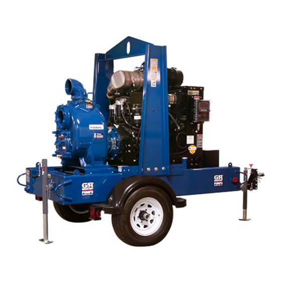
- Page 1 OM-07376-01 October 5, 2020 INSTALLATION, OPERATION, AND MAINTENANCE MANUAL WITH PARTS LIST SUPER T SERIES PUMP MODEL T4A60S-C2.2T FT4 GORMAN‐RUPP PUMPS www.grpumps.com 2020 Gorman‐Rupp Pumps Printed in U.S.A.
- Page 2 Register your new Gorman‐Rupp pump online at www.grpumps.com Valid serial number and e‐mail address required. The engine exhaust from this product contains chemicals known to the State of California to cause cancer, birth defects or other reproductive harm. RECORD YOUR PUMP MODEL AND SERIAL NUMBER Please record your pump model and serial number in the spaces provided below.
-
Page 3: Table Of Contents
TABLE OF CONTENTS INTRODUCTION ..........PAGE I - 1 SAFETY ‐... - Page 4 TABLE OF CONTENTS (continued) Manual Stopping ............PAGE C - 4 Automatic Stopping .
-
Page 5: Introduction
SUPER T SERIES OM-07376 INTRODUCTION Thank You for purchasing a Gorman‐Rupp pump. HAZARD AND INSTRUCTION Read this manual carefully to learn how to safely DEFINITIONS install and operate your pump. Failure to do so could result in personal injury or damage to the The following are used to alert maintenance per... -
Page 6: Safety - Section A
SUPER T SERIES OM-07376 SAFETY ‐ SECTION A This information applies to Super T Se ing away from the unit to prevent injury ries engine driven pumps. Refer to the during automatic operation. Disconnect manual accompanying the engine be the positive battery cable before per fore attempting to begin operation. - Page 7 OM-07376 SUPER T SERIES When operating internal combustion engines in an enclosed area, make cer tain that exhaust fumes are piped to the outside. These fumes contain carbon Do not operate the pump against a monoxide, a deadly gas that is color closed discharge valve for long periods less, tasteless, and odorless.
-
Page 8: Installation - Section B
SUPER T SERIES OM-07376 INSTALLATION - SECTION B Review all SAFETY information in Section A. specific application. Since the pressure supplied to the pump is critical to performance and safety, Since pump installations are seldom identical, this be sure to limit the incoming pressure to 50% of the section offers only general recommendations and maximum permissible operating pressure as practices required to inspect, position, and ar... -
Page 9: Preinstallation Inspection
OM-07376 SUPER T SERIES Before installing the battery, clean the positive and PREINSTALLATION INSPECTION negative cable connectors, and the battery termi nals. Secure the battery by tightening the The pump assembly was inspected and tested be holddown brackets. The terminals and clamps fore shipment from the factory. -
Page 10: Clearance
SUPER T SERIES OM-07376 the brake and blocking the wheels before attempt place by tightening the flange bolts and/or cou ing to operate the pump. plings. Lines near the pump must be independently sup To ensure sufficient lubrication and fuel supply to ported to avoid strain on the pump which could the engine, do not position the pump and engine cause excessive vibration, decreased bearing life,... -
Page 11: Sealing
OM-07376 SUPER T SERIES three or four times the cross section of the suction If it is necessary to position inflow close to the suc line, and the openings will not permit passage of tion inlet, install a baffle between the inflow and the solids larger than the solids handling capability of suction inlet at a distance 1‐1/2 times the diameter the pump. -
Page 12: Float Switches
SUPER T SERIES OM-07376 Figure 2. Recommended Minimum Suction Line Submergence vs. Velocity FLOAT SWITCHES above the point where it bends along the bot tom. Direct the suction line toward the flow, and the float(s) away from the flow. If a stand Installation pipe is available, attach the float switch cable to the standpipe in the sump at the approxi... -
Page 13: Optional Submersible Transducer
OM-07376 SUPER T SERIES ENGINE (0.9) CONTROL (.76) (Emptying) (0.6) (Filling) (.46) OPERATING (0.3) RANGE CABLE (See Table Below) TETHER (.15) POINT (Emptying) (0.3) (0.6) (0.9) (1.2) APPROXIMATE FREE CORD LENGTH IN FT. (M) 1.25” Pipe (Filling) (Not Furnished) Figure 3. Float Switch Data OPTIONAL SUBMERSIBLE above the point where it bends along the bot... -
Page 14: Discharge Lines
SUPER T SERIES OM-07376 SUCTION LINE DISCHARGE LINE SIGNAL CABLE (ATTACH TO SUCTION LINE) SUCTION SUBMERSIBLE STRAINER TRANSDUCER (DOWNSTREAM FROM SUCTION) FLOW Figure 4. Typical Submersible Transducer Installation DISCHARGE LINES Siphoning If the application involves a high discharge head, gradually close the discharge Do not terminate the discharge line at a level lower throttling valve before stopping the pump. -
Page 15: Automatic Air Release Valve
OM-07376 SUPER T SERIES affect pump discharge capacity; however, the by lift station), if a manual shut‐off valve is in pass line should be at least 1 inch (25,4 mm) in di stalled anywhere in a bypass line, it must ameter to minimize the chance of plugging. -
Page 16: Air Release Valve Installation
SUPER T SERIES OM-07376 Consult the manual accompanying the Air Release Air Release Valve Installation Valve for additional information on valve installation The Automatic Air Release Valve must be inde and performance. pendently mounted in a horizontal position be tween the pump discharge port and the inlet side of the discharge check valve (see Figure 5). -
Page 17: Operation - Section C
OM-07376 SUPER T SERIES OPERATION - SECTION C OPERATION Review all SAFETY information in Section A. Make sure the pump is level. Lower jack Follow the instructions on all tags, labels and stands and chock the wheels, if so decals attached to the pump. equipped. -
Page 18: Routine Operation
OM-07376 SUPER T SERIES Add liquid to the pump casing when: continuous operating speed for this pump. 1. The pump is being put into service for the first time. A Gorman‐Rupp automatic air release valve may 2. The pump has not been used for a consider be installed in a bypass line, or the bypass line may able length of time. -
Page 19: Operation In Extreme Heat
OM-07376 SUPER T SERIES OPERATION IN EXTREME HEAT The safety shutdown system will automatically stop the unit if engine operating temperature ex Allow an over‐heated pump to com ceeds design limits. If engine over‐temperature pletely cool before servicing. Do not re shutdown occurs, allow the unit to cool before re... -
Page 20: Stopping
OM-07376 SUPER T SERIES Should any of the safety features cause the engine 5. Close the suction and discharge to shut down, the cause must be determined and valves. corrected before putting the unit back into service. 6. Vent the pump slowly and cau tiously. - Page 21 OM-07376 SUPER T SERIES tenance and Repair). Bearing overheating can Consult the manual accompanying the engine, also be caused by shaft misalignment and/or ex and change the oil filter periodically as indicated. If cessive vibration. operated under extremely dusty conditions, change the filter more frequently.
- Page 22 SUPER T SERIES OM-07376 TROUBLESHOOTING - SECTION D Review all SAFETY information in Section A. 5. Close the suction and discharge valves. 6. Vent the pump slowly and cau tiously. 7. Drain the pump. Before attempting to open or service the pump: 1.
- Page 23 OM-07376 SUPER T SERIES Table 1. Trouble Shooting Chart (cont.) TROUBLE POSSIBLE CAUSE PROBABLE REMEDY PUMP STOPS OR FAILS Leaking or worn seal or pump gas Check pump vacuum. Replace ket. leaking or worn seal or gasket. TO DELIVER RATED FLOW OR PRESSURE Strainer clogged.
- Page 24 SUPER T SERIES OM-07376 Table 1. Trouble Shooting Chart (cont.) TROUBLE POSSIBLE CAUSE PROBABLE REMEDY BEARINGS RUN TOO Bearing temperature is high, but Check bearing temperature regular within limits. ly to monitor any increase. Low or incorrect lubricant. Check for proper type and level of lubricant.
- Page 25 OM-07376 SUPER T SERIES Preventive Maintenance Schedule Service Interval* Item Daily Weekly Monthly Semi‐ Annually Annually General Condition (Temperature, Unusual Noises or Vibrations, Cracks, Leaks, Loose Hardware, Etc.) Pump Performance (Gauges, Speed, Flow) Bearing Lubrication Seal Lubrication (And Packing Adjustment, If So Equipped) V‐Belts (If So Equipped) Air Release Valve Plunger Rod (If So Equipped)
- Page 26 SUPER T SERIES OM-07376 PUMP MAINTENANCE AND REPAIR ‐ SECTION E MAINTENANCE AND REPAIR OF THE WEARING PARTS OF THE PUMP WILL MAINTAIN PEAK OPERATING PERFORMANCE. STANDARD PERFORMANCE FOR PUMP MODEL T4A60S-C2.2T FT4 Based on 70 F (21 C) clear water at sea level with minimum suction lift.
- Page 27 OM-07376 SUPER T SERIES ILLUSTRATION PARTS PAGE Figure 1. Pump Model T4A60S-C2.2T FT4 PAGE E - 2 MAINTENANCE & REPAIR...
- Page 28 SUPER T SERIES OM-07376 PARTS LIST Pump Model T4A60S-C2.2T FT4 (From S/N 1730288 Up) ITEM PART PART NAME NUMBER PUMP END ASSEMBLY 46186-527 POWER UNIT CAT C2.2T FT4 46143-239 PUMP MOUNTING KIT 48157-117 BATTERY 12V 29331-527 NOT SHOWN: G-R DECAL GR-06 CAUTION DECAL 38816-169...
- Page 29 OM-07376 SUPER T SERIES ILLUSTRATION DETAIL A 21 20 12 13 Figure 2. Power Unit Kit PAGE E - 4 MAINTENANCE & REPAIR...
- Page 30 SUPER T SERIES OM-07376 PARTS LIST Power Unit Kit ITEM PART PART NAME NUMBER BASE/FUEL TANK ASSEMBLY 41553-053 24150 CAT C2.2T FT4 ENGINE 29236-410 CONTROL PANEL INSTALLATION KIT 48122-563 LIFTING BAIL KIT 48274-811 HOSE .62 ID X 65" LG 18513-304 HOSE CLAMP 26518-666 CABLE TIE...
- Page 31 OM-07376 SUPER T SERIES ILLUSTRATION Figure 3. Pump End Assembly PAGE E - 6 MAINTENANCE & REPAIR...
- Page 32 SUPER T SERIES OM-07376 PARTS LIST Pump End Assembly ITEM PART NAME PART ITEM PART NAME PART NUMBER NUMBER PUMP CASING SEE NOTE BELOW O-RING S1472 PIPE PLUG P04 15079 INSPECT COVER ASSY 42111-451 GASKET 25113-034 -PRESS RELIEF VLV 26662-005 4"...
- Page 33 OM-07376 SUPER T SERIES ILLUSTRATION Ç Ç Ç Ç Ç Ç Ç Ç Ç Ç Ç Ç Ñ Ñ Ñ Ï Ï Ç Ç Ç Ç Ñ Ñ Ñ Ï Ï Ï Ï Ï Ï Ï Ï Ï Ñ Ñ Ñ Ï...
- Page 34 SUPER T SERIES OM-07376 PARTS LIST Repair Rotating Assembly ITEM PART PART NAME NUMBER IMPELLER 10528 11010 ADJ SHIM SET 37J 17090 1.50 SEAL ASSY 46513-151 O‐RING 25154-022 SEAL PLATE 38272-234 10010 GASKET 10959G 20000 OIL SEAL S1352 PIPE PLUG PC20 10009 LOCK WASHER J08 15991...
- Page 35 OM-07376 SUPER T SERIES ILLUSTRATION Ì Ì Ì Ì Ì Ì Ì Ì Ì Ì Ì Ì Ì Ì Ñ Ñ Ñ Ñ Ñ Ñ Ñ Ì Ì Ì Ì Ì Ì Ì Ñ Ñ Ñ Ñ Ñ Ñ Ñ Ì...
- Page 36 SUPER T SERIES OM-07376 to ensure that it will remain inoperative. Close all PUMP AND SEAL DISASSEMBLY valves in the suction and discharge lines. AND REASSEMBLY For engine disassembly and repair, consult the lit Review all SAFETY information in Section A. erature supplied with the engine, or contact your local engine representative.
- Page 37 OM-07376 SUPER T SERIES Inspect the wear plate and replace it if badly scored necessary and keep personnel away or worn. To remove the wear plate, disengage the from suspended objects. hardware (24 and 25). Inspect the back cover and wear plate O‐rings (18 and 19) and replace it if damaged or worn.
- Page 38 SUPER T SERIES OM-07376 the shaft. To remove the coupling from the shaft, shaft (26) with the “V” notch positioned over the unscrew the two allen head setscrews from the shaft key. bushing (2). Screw one of the setscrews into the With the impeller rotation still blocked, see Figure 6 puller hole on the circumference of the bushing.
- Page 39 OM-07376 SUPER T SERIES Seal Removal NOTE An optional disassembly tool is available from the (Figure 4) factory. If the tool is used, follow the instructions packed with it. A similar tool may be assembled us Slide the integral shaft sleeve and rotating portion ing 1/2‐inch pipe (schedule 80 steel or malleable of the seal off the shaft as a unit.
- Page 40 SUPER T SERIES OM-07376 Pry or press the oil seals (7) from the bearing hous housing. Replace the bearings, shaft, or bearing ing. housing if the proper bearing fit is not achieved. If bearing replacement is required, remove the out After removing the shaft and bearings, clean and board bearing snap ring (23) and use a bearing inspect the bearings in place as follows.
- Page 41 OM-07376 SUPER T SERIES The bearings may be heated to ease installation. With the lip seal sleeve in place, lubricate the lip An induction heater, hot oil bath, electric oven, or seal area of the shaft, and slide the shaft and as hot plate may be used to heat the bearings.
- Page 42 SUPER T SERIES OM-07376 Reusing an old seal could result in prema ture failure. To ease installation of the seal, lubricate the shaft sleeve O‐ring (14) and the external stationary seat A new seal assembly should be installed O‐ring with a very small amount of “P-80 Emul...
- Page 43 OM-07376 SUPER T SERIES Lubricate the external stationary seat O‐ring with STATIONARY SEAT FULLY SEATED IN light oil. Slide the seal assembly onto the shaft until SEAL PLATE BORE the external stationary seat O‐ring engages the bore in the seal plate. Clean and inspect the impeller as described in Im...
- Page 44 SUPER T SERIES OM-07376 when reusing an old seal. The rubber bel NOTE lows will adhere to the sleeve during use, At the slightest sign of binding, immediately back and attempting to separate them could the impeller off, and check the threads for dirt. Do damage the bellows.
- Page 45 OM-07376 SUPER T SERIES Suction Check Valve Installation USE TWO USE TWO REMAINING OPPOSING ADJUSTING SCREWS AND BACK COVER NUTS LOCKING COLLARS TO (Figure 3) SET FACE CLEARANCE TO PRESS BACK COVER INTO PUMP Inspect the check valve assembly (40) and replace CASING it if badly worn.
- Page 46 SUPER T SERIES OM-07376 they engage the pump casing. Install the locking coupling to fully engage when the drive collars (36) and hardware (15 and 33). Reinstall the flange is secured to the engine bellhous back cover nuts. ing, without pre‐loading the bearings. Be sure the wear plate does not scrape against the With the flexible portion of the coupling and the impeller.
- Page 47 OM-07376 SUPER T SERIES Remove the fill cover assembly (12, Figure 3) and dividual components only. Additional fill the pump casing with clean liquid. Reinstall the weight may result in damage to the fill cover and tighten it. Refer to OPERATION, Sec pump or failure of the eye bolt.
- Page 48 For Warranty Information, Please Visit www.grpumps.com/warranty or call: U.S.: 419-755-1280 Canada: 519-631-2870 International: +1-419-755-1352 GORMAN‐RUPP PUMPS...
Need help?
Do you have a question about the SUPER T T4A60S-C2.2T FT4 and is the answer not in the manual?
Questions and answers