
Related Manuals for GORMAN-RUPP PUMPS Super T T4A60S-4LET2T FT4-ESP Series


Summary of Contents for GORMAN-RUPP PUMPS Super T T4A60S-4LET2T FT4-ESP Series
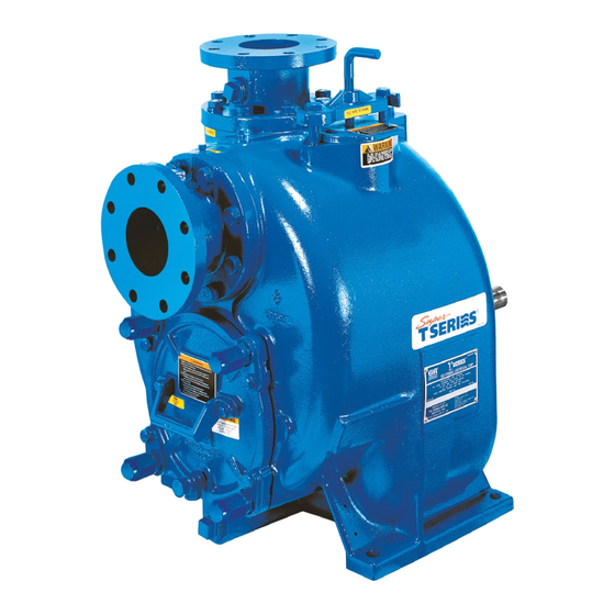
- Page 1 OM-07116-01 June 20, 2017 INSTALLATION, OPERATION, AND MAINTENANCE MANUAL WITH PARTS LIST SUPER T SERIESr PUMP MODEL T4A60S‐4LE2T FT4‐ESP GORMAN‐RUPP PUMPS www.grpumps.com 2017 Gorman‐Rupp Pumps Printed in U.S.A.
- Page 2 Register your new Gorman‐Rupp pump online at www.grpumps.com Valid serial number and e‐mail address required. The engine exhaust from this product contains chemicals known to the State of California to cause cancer, birth defects or other reproductive harm. RECORD YOUR PUMP MODEL AND SERIAL NUMBER Please record your pump model and serial number in the spaces provided below.
-
Page 3: Table Of Contents
TABLE OF CONTENTS INTRODUCTION ..........PAGE I - 1 SAFETY ‐... - Page 4 TABLE OF CONTENTS (continued) Manual Stopping ............PAGE C - 4 Automatic Stopping .
-
Page 5: Introduction
SUPER T SERIES OM-07116 INTRODUCTION Thank You for purchasing a Gorman‐Rupp pump. HAZARD AND INSTRUCTION Read this manual carefully to learn how to safely DEFINITIONS install and operate your pump. Failure to do so could result in personal injury or damage to the The following are used to alert maintenance per... -
Page 6: Safety - Section A
SUPER T SERIES OM-07116 SAFETY ‐ SECTION A This information applies to Super T Se forming any maintenance. Failure to do riesr engine driven pumps. Refer to the so may result in serious personal injury. manual accompanying the engine be fore attempting to begin operation. - Page 7 OM-07116 SUPER T SERIES deteriorate, and the liquid could come stands and chock the wheels, if so to a boil, build pressure, and cause the equipped. Use caution when positioning pump casing to rupture or explode. the skid‐mounted unit to prevent damage to the fuel tank.
-
Page 8: Installation - Section B
SUPER T SERIES OM-07116 INSTALLATION - SECTION B Review all SAFETY information in Section A. specific application. Since the pressure supplied to the pump is critical to performance and safety, Since pump installations are seldom identical, this be sure to limit the incoming pressure to 50% of the section offers only general recommendations and maximum permissible operating pressure as practices required to inspect, position, and ar... -
Page 9: Battery Specifications And Installation
OM-07116 SUPER T SERIES ing, check for loose hardware at mating sur POSITIONING PUMP faces. c. Carefully read all tags, decals, and markings on the pump assembly, and perform all duties indicated. Death or serious personal injury and damage to the pump or components can occur if proper lifting procedures d. -
Page 10: Clearance
SUPER T SERIES OM-07116 to 30 off horizontal for intermittent operation lines are used, they should have adequate support only; however, the engine manufacturer should be to secure them when filled with liquid and under consulted for continuous operation at angles pressure. -
Page 11: Sealing
OM-07116 SUPER T SERIES Sealing of the suction pipe. The baffle will allow entrained air to escape from the liquid before it is drawn into Since even a slight leak will affect priming, head, the suction inlet. and capacity, especially when operating with a If two suction lines are installed in a single sump, high suction lift, all connections in the suction line the flow paths may interact, reducing the efficiency... -
Page 12: Float Switches
SUPER T SERIES OM-07116 above the point where it bends along the bot FLOAT SWITCHES tom. Direct the suction line toward the flow, and the float(s) away from the flow. If a stand Installation pipe is available, attach the float switch cable to the standpipe in the sump at the approxi... - Page 13 OM-07116 SUPER T SERIES a. Handle the signal cable and transducer with cific gravity, the reading on the EPS should be care during installation. Carefully lower the divided by the specific gravity of the mea transducer into the wet well or sump; do not sured medium to obtain the actual level.
-
Page 14: Discharge Lines
SUPER T SERIES OM-07116 In low discharge head applications (less than 30 DISCHARGE LINES feet (9,1 m)), it is recommended that the bypass line be run back to the wet well, and located 6 Siphoning inches below the water level or cut‐off point of the low level pump. -
Page 15: Automatic Air Release Valve
OM-07116 SUPER T SERIES through the bypass line and then close automati cally when the pump is fully primed and pumping at full capacity. A manual shut‐off valve should not be installed in any bypass line. A manual shut‐off valve may inadvertently be left closed during operation. -
Page 16: Alignment
SUPER T SERIES OM-07116 Connect the valve outlet to a bleed line which fold pipe. Contact your Gorman‐Rupp distributor or slopes back to the wet well or sump. The bleed line the Gorman‐Rupp Company for information about must be the same size as the outlet opening or installation of an Automatic Air Release Valve for larger, depending on which Air Release Valve is be... -
Page 17: Operation - Section C
OM-07116 SUPER T SERIES OPERATION - SECTION C OPERATION Review all SAFETY information in Section A. Make sure the pump is level. Lower jack Follow the instructions on all tags, labels and stands and chock the wheels, if so decals attached to the pump. equipped. -
Page 18: Routine Operation
OM-07116 SUPER T SERIES Add liquid to the pump casing when: continuous operating speed for this pump. 1. The pump is being put into service for the first time. A Gorman‐Rupp automatic air release valve may 2. The pump has not been used for a consider be installed in a bypass line, or the bypass line may able length of time. -
Page 19: Operation In Extreme Heat
OM-07116 SUPER T SERIES the source of the leak, check the point of installa OPERATION IN EXTREME HEAT tion of the vacuum gauge. The safety shutdown system will automatically Liquid Temperature And Overheating stop the unit if engine operating temperature ex ceeds design limits. -
Page 20: Stopping
OM-07116 SUPER T SERIES STOPPING shutdown before putting the unit back into service. Consult the factory for ad ditional information. Manual Stopping PERIODIC CHECKS In the manual mode, reduce the throttle speed slowly, and allow the engine to idle briefly before Seal Cavity and Bearing Lubrication turning the keyswitch to `OFF'. - Page 21 OM-07116 SUPER T SERIES Consult the manual accompanying the engine, for approximately one minute; this will remove any and change the oil filter periodically as indicated. If remaining liquid that could freeze the pump rotat operated under extremely dusty conditions, ing parts.
- Page 22 SUPER T SERIES OM-07116 TROUBLESHOOTING - SECTION D Review all SAFETY information in Section A. 5. Close the suction and discharge valves. 6. Vent the pump slowly and cau tiously. 7. Drain the pump. Before attempting to open or service the pump: 1.
- Page 23 OM-07116 SUPER T SERIES Table 1. Trouble Shooting Chart (cont.) TROUBLE POSSIBLE CAUSE PROBABLE REMEDY PUMP STOPS OR FAILS Leaking or worn seal or pump gas Check pump vacuum. Replace ket. leaking or worn seal or gasket. TO DELIVER RATED FLOW OR PRESSURE Strainer clogged.
- Page 24 SUPER T SERIES OM-07116 Table 1. Trouble Shooting Chart (cont.) TROUBLE POSSIBLE CAUSE PROBABLE REMEDY BEARINGS RUN TOO Bearing temperature is high, but Check bearing temperature regular within limits. ly to monitor any increase. Low or incorrect lubricant. Check for proper type and level of lubricant.
- Page 25 OM-07116 SUPER T SERIES Preventive Maintenance Schedule Service Interval* Item Daily Weekly Monthly Semi‐ Annually Annually General Condition (Temperature, Unusual Noises or Vibrations, Cracks, Leaks, Loose Hardware, Etc.) Pump Performance (Gauges, Speed, Flow) Bearing Lubrication Seal Lubrication (And Packing Adjustment, If So Equipped) V‐Belts (If So Equipped) Air Release Valve Plunger Rod (If So Equipped)
- Page 26 SUPER T SERIES OM-07116 PUMP MAINTENANCE AND REPAIR ‐ SECTION E MAINTENANCE AND REPAIR OF THE WEARING PARTS OF THE PUMP WILL MAINTAIN PEAK OPERATING PERFORMANCE. STANDARD PERFORMANCE FOR PUMP MODEL T4A60S-4LE2T FT4-ESP Based on 70 F (21 C) clear water at sea level Contact the Gorman‐Rupp Company to verify per...
- Page 27 OM-07116 SUPER T SERIES ILLUSTRATION PARTS PAGE Figure 1. Pump Model T4A60S-4LE2T FT4-ESP PAGE E - 2 MAINTENANCE & REPAIR...
- Page 28 SUPER T SERIES OM-07116 PARTS LIST Pump Model T4A60S-4LE2T FT4-ESP (From S/N 1659564 Up) If your pump serial number is followed by an “N”, your pump is NOT a standard production model. Contact the Gorman‐Rupp Company to verify part numbers. ITEM PART PART NAME...
- Page 29 OM-07116 SUPER T SERIES ILLUSTRATION PARTS PAGE GREEN WIRE GREEN WIRE BLACK WIRE BLACK WIRE SILVER PIN SOCKET RED WIRE WHITE WIRE SILVER PIN SOCKET RED WIRE WHITE WIRE 1.25 WIRE END DETAIL Figure 2. Pump Model T4A60S-4LE2T FT4-ESP (cont'd) PAGE E - 4 MAINTENANCE &...
- Page 30 SUPER T SERIES OM-07116 PARTS LIST Pump Model T4A60S-4LE2T FT4-ESP (From S/N 1659564 Up) If your pump serial number is followed by an “N”, your pump is NOT a standard production model. Contact the Gorman‐Rupp Company to verify part numbers. ITEM PART PART NAME...
- Page 31 OM-07116 SUPER T SERIES ILLUSTRATION DETAIL A Figure 3. Power Unit Kit PAGE E - 6 MAINTENANCE & REPAIR...
- Page 32 SUPER T SERIES OM-07116 PARTS LIST Power Unit Kit ITEM PART PART NAME NUMBER BASE/FUEL TANK ASSEMBLY 41553-055 24150 ISUZU 4LE2T ENGINE FT4 29223-401 CONTROL PANEL INSTALLATION KIT 48122-563 LIFTING BAIL KIT 48274-811 LOCK WASHER J10 15991 HEX NUT D10 15991 FLAT WASHER K10 15991 HEX HEAD CAP SCREW...
- Page 33 OM-07116 SUPER T SERIES ILLUSTRATION 30 15 Figure 4. Pump End Assembly PAGE E - 8 MAINTENANCE & REPAIR...
- Page 34 SUPER T SERIES OM-07116 PARTS LIST Pump End Assembly ITEM PART NAME PART ITEM PART NAME PART NUMBER NUMBER PUMP CASING SEE NOTE BELOW GASKET ‐ SUCT FLANGE 11389G 19370 REPAIR ROTATING ASSY 44163-347 4'' FLAP VALVE ASSY 46411-062 PIPE PLUG P04 15079 FILL COVER PLATE ASSY 42111-344 LOCK WASHER...
- Page 35 OM-07116 SUPER T SERIES ILLUSTRATION SEAL AREA DETAIL Figure 5. Repair Rotating Assembly PAGE E - 10 MAINTENANCE & REPAIR...
- Page 36 SUPER T SERIES OM-07116 PARTS LIST Repair Rotating Assembly ITEM PART PART NAME NUMBER IMPELLER 10528 11010 IMPELLER ADJ SHIM SET 37J 17090 CARTRIDGE SEAL ASSEMBLY 46513-151 SEAL PLATE 38272-234 10010 SEAL PLATE GASKET 10959G 20000 OIL SEAL S1352 OIL SEAL S1352 OIL SEAL S1352...
- Page 37 OM-07116 SUPER T SERIES ILLUSTRATION 0.00 IN. 0.00 MM Figure 6. Drive Assembly PARTS LIST ITEM PART PART NAME NUMBER COUPLING KIT 48112-005 -BUSHING 24131-496 -COUPLING ASSEMBLY 24391-105 -LOCKWASHER 21171-536 -SOCKET HD CAPSCREW BD0606-1/2 15991 -SOCKET HD CAPSCREW 22644-220 HEX HD CAPSCREW B0605 15991 HEX HD CAPSCREW 22645-164...
- Page 38 SUPER T SERIES OM-07116 PUMP AND SEAL DISASSEMBLY the owner/maintenance personnel to ensure that only safe, established main AND REASSEMBLY tenance procedures are used, and that any procedures not addressed in this Review all SAFETY information in Section A. manual are performed only after estab lishing that neither personal safety nor Follow the instructions on all tags, label and de...
- Page 39 OM-07116 SUPER T SERIES necessary and keep personnel away NOTE from suspended objects. Further disassembly of the check valve is not re quired since it must be replaced as a complete unit. Individual parts are not sold separately. Separating Intermediate And Drive Assembly Use Only Genuine Gorman-Rupp re...
- Page 40 SUPER T SERIES OM-07116 Remove any leveling shims used under the casing Turn mounting feet. Tie and tag the shims for ease of Counterclockwise reassembly. Move the pump end to a clean, well equipped shop area for further disassembly. Lathe Dog Arm Loosening Impeller (Figure 5) “V”...
- Page 41 OM-07116 SUPER T SERIES An alternate method of removing the stationary seal components is to remove the hardware (7 and 8) and separate the seal plate (4) and gasket (5) from the bearing housing (9). Position the seal plate on a flat surface with the impeller side down. APPROX.
- Page 42 SUPER T SERIES OM-07116 Shaft and Bearing Reassembly and Installation be cleaned and inspected in place. It is strongly recommended that the bearings (Figure 5) be replaced any time the shaft and bear ings are removed. Clean the bearing housing, shaft and all compo nent parts (except the bearings) with a soft cloth soaked in cleaning solvent.
- Page 43 OM-07116 SUPER T SERIES NOTE If a hot oil bath is used to heat the bearings, both the oil and the container must be absolutely clean. If the oil has been previously used, it must be thor When installing the shaft and bearings into oughly filtered.
- Page 44 SUPER T SERIES OM-07116 nal stationary seat O‐ring with a very small amount Reusing an old seal could result in prema of light lubricating oil. See Figure 9 for seal part ture failure. identification. To ease installation of the seal, lubricate the exter MAINTENANCE &...
- Page 45 OM-07116 SUPER T SERIES RETAINER SEAL PLATE SPRING O‐RINGS IMPELLER SLEEVE O‐RING IMPELLER SHIMS IMPELLER SHAFT INTEGRAL SHAFT ROTATING STATIONARY SLEEVE BELLOWS ELEMENT ELEMENT SHEAR SPRING RING (SHEARED) CENTERING WASHER STATIONARY DRIVE BAND SEAT Figure 9. Seal Assembly This seal is not designed for operation at New cartridge seal assemblies may be equipped with mylar storage tabs between temperatures above 160...
- Page 46 SUPER T SERIES OM-07116 Continue to screw the impeller onto the shaft. This proper clearance as described in Impeller Instal will press the stationary seat into the seal plate lation and Adjustment. bore. If necessary to reuse an old seal in an emergen cy, carefully separate the rotating and stationary O‐RING ENGAGED WITH SEAL PLATE...
- Page 47 OM-07116 SUPER T SERIES Slide the rotating portion of the seal (consisting of Rotating Assembly Installation the integral shaft sleeve, spring centering washer, (Figure 4) spring, bellows and retainer, and rotating element) onto the shaft until the seal faces contact. NOTE If the pump has been completely disassembled, it Proceed with Impeller Installation and Adjust...
- Page 48 SUPER T SERIES OM-07116 replace the respective gaskets, apply `Permatex Screw the four adjusting screws (18) into the Aviation No. 3 Form‐A‐Gasket' or equivalent com tapped holes in the back cover plate until they are pound to the mating surfaces, and secure them to just flush with the machined surface on the back the pump casing with the attaching hardware.
- Page 49 OM-07116 SUPER T SERIES rotating assembly to the pump casing. Perform the Using a suitable lifting device, position the pump back cover adjustment procedure described end so the flexible portion of the coupling seats in above to obtain the proper face clearance. side the outer ring attached to the engine flywheel.
- Page 50 SUPER T SERIES OM-07116 replace this valve with a substitute which has not tergent oil to the middle of the sight gauge (14) and been specified or provided by the Gorman‐Rupp maintain it at the middle of the gauge. Clean and Company.
- Page 51 For Warranty Information, Please Visit www.grpumps.com/warranty or call: U.S.: 419-755-1280 Canada: 519-631-2870 International: +1-419-755-1352 GORMAN‐RUPP PUMPS...
Need help?
Do you have a question about the Super T T4A60S-4LET2T FT4-ESP Series and is the answer not in the manual?
Questions and answers