Table of Contents
Advertisement
Quick Links
CDSW
OM-03182-OB01
January 9, 1989
Rev. I 04/23/02
INSTALLATION, OPERATION,
AND MAINTENANCE MANUAL
WITH PARTS LIST
T SERIES PUMP
MODEL
T4B65---B
INCLUDING: /F
THE GORMAN-RUPP COMPANY D MANSFIELD, OHIO
GORMAN-RUPP OF CANADA LIMITED
ST. THOMAS, ONTARIO, CANADA
D
Printed in U.S.A.
E
Copyright by the Gorman-Rupp Company
Advertisement
Table of Contents

Related Manuals for GORMAN-RUPP PUMPS T4B65-B


Summary of Contents for GORMAN-RUPP PUMPS T4B65-B
- Page 1 CDSW OM-03182-OB01 January 9, 1989 Rev. I 04/23/02 INSTALLATION, OPERATION, AND MAINTENANCE MANUAL WITH PARTS LIST T SERIES PUMP MODEL T4B65---B INCLUDING: /F THE GORMAN-RUPP COMPANY D MANSFIELD, OHIO GORMAN-RUPP OF CANADA LIMITED ST. THOMAS, ONTARIO, CANADA Printed in U.S.A. Copyright by the Gorman-Rupp Company...
- Page 2 TABLE OF CONTENTS INTRODUCTION ..........PAGE I --- 1 SAFETY --- SECTION A .
-
Page 3: Table Of Contents
TABLE OF CONTENTS (continued) TROUBLESHOOTING --- SECTION D ......PAGE D --- 1 PREVENTIVE MAINTENANCE . - Page 4 T SERIES OM -- 03182 INTRODUCTION This Installation, Operation, and Maintenance valve. The pump is designed for handling chemical manual is designed to help you achieve the best and low Ph resistance residues and slurries con- performance and longest life from your Gorman- taining large entrained solids.
- Page 5 T SERIES OM -- 3182 SAFETY --- SECTION A This information applies to the T Series als which may damage the pump or en- basic pumps. Gorman-Rupp has no danger personnel as a result of pump control over or particular knowledge of failure.
- Page 6 OM -- 03182 T SERIES deteriorate, and the liquid could come to a boil, build pressure, and cause the pump casing to rupture or explode. Use lifting and moving equipment in good repair and with adequate capacity to prevent injuries to personnel or dam- age to equipment.
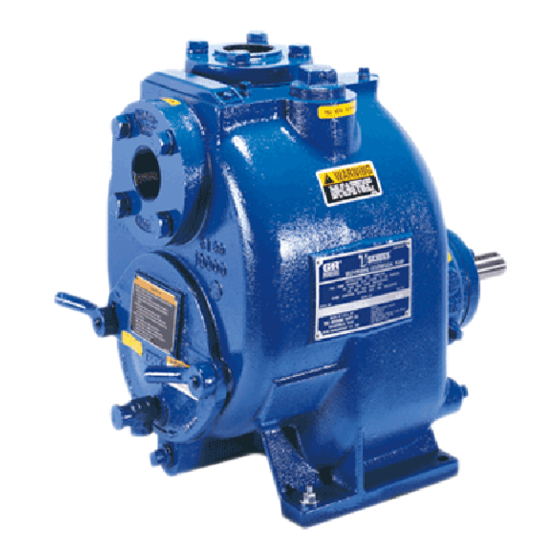
- Page 7 See Figure 1 for the approximate physical dimen- configuration, and priming must be tailored to the sions of this pump. OUTLINE DRAWING Figure 1. Pump Model T4B65-B INSTALLATION PAGE B -- 1...
- Page 8 OM -- 03182 T SERIES PREINSTALLATION INSPECTION POSITIONING PUMP Lifting The pump assembly was inspected and tested be- fore shipment from the factory. Before installation, Use lifting equipment with a capacity of at least inspect the pump for damage which may have oc- 2,900 pounds (1315,4 kg).
- Page 9 T SERIES OM -- 03182 Fittings compatible with the liquid being pumped. If hose is used in suction lines, it must be the rigid-wall, rein- Suction lines should be the same size as the pump forced type to prevent collapse under suction. Us- inlet.
- Page 10 OM -- 03182 T SERIES Suction Line Positioning If it is necessary to position inflow close to the suc- tion inlet, install a baffle between the inflow and the The depth of submergence of the suction line is suction inlet at a distance 1 1/2 times the diameter critical to efficient pump operation.
- Page 11 T SERIES OM -- 03182 from excessive shock pressure and reverse rota- It is also recommended that pipe unions be in- tion when it is stopped. stalled at each 90_ elbow in a bypass line to ease disassembly and maintenance. In high discharge head applications (more than 30 feet), an excessive amount of liquid may be by- passed and forced back to the wet well under the...
- Page 12 OM -- 03182 T SERIES drain the liquid from the pump by re- presses the spring and closes the valve (Figure 4). The valve will remain closed, reducing the bypass moving the casing drain plug. Use cau- of liquid to 1 to 5 gallons (3.8 to 19 liters) per min- tion when removing the plug to prevent ute, until the pump loses its prime or stops.
- Page 13 T SERIES OM -- 03182 DISCHARGE PIPE CLEAN-OUT COVER INSTALL AIR RELEASE VALVE IN HORIZONTAL POSITION DISCHARGE CHECK VALVE 90_ LONG RADIUS ELBOW SUPPORT PUMP DISCHARGE BRACKET SELF-PRIMING CENTRIFUGAL PUMP BLEED LINE 1” (25,4 MM) DIA. MIN. (CUSTOMER FURNISHED) EXTEND 6” SUCTION LINE (152,4 MM)
- Page 14 OM -- 03182 T SERIES When checking alignment, disconnect the power source to ensure that the pump will remain inoperative. Adjusting the alignment in one direction Figure 6B. Aligning Non-Spider may alter the alignment in another direc- Type Couplings tion. check each procedure after altering alignment.
- Page 15 T SERIES OM -- 03182 excessive power loss and possible bearing failure. Select pulleys that will match the proper speed ra- tio; overspeeding the pump may damage both pump and power source. Do not operate the pump without the guard in place over the rotating parts exposed rotating parts can catch cloth- ing, fingers, or tools, causing severe in- jury to personnel.
- Page 16 OM -- 03182 T-SERIES OPERATION --- SECTION C Review all SAFETY information in Section A. Follow the instructions on all tags, labels and de- cals attached to the pump. Never operate this pump unless there is liquid in the pump casing. The pump will not prime when dry.
- Page 17 OM -- 03182 T-SERIES fected by incorrect rotation. If pump performance sprinkler heads, and any other fixtures connected is not within the specified limits (see the curve on to the line. When the discharge line is completely page E-1), check the direction of power source ro- filled, adjust the throttling valve to the required flow tation before further troubleshooting.
- Page 18 OM -- 03182 T-SERIES with great force. After the pump cools, Open the suction line, and read the vacuum gauge drain the liquid from the pump by re- with the pump primed and at operation speed. Shut off the pump. The vacuum gauge reading will moving the casing drain plug.
- Page 19 OM -- 03182 T-SERIES Temperatures up to 160_F (71_ C) are considered to operate properly. Make certain that the bearing normal for bearings, and they can operate safely to lubricant is of the proper viscosity and at the cor- at least 180_F (82_ C). rect level (see LUBRICATION in MAINTENANCE AND REPAIR).
-
Page 20: Troubleshooting
T SERIES OM -- 03182 TROUBLESHOOTING --- SECTION D Review all SAFETY information in Section A. Before attempting to open or service the pump: 1. Familiarize yourself with this manual. 2. Lock out or disconnect the power source to ensure that the pump will remain inoperative. - Page 21 OM -- 03182 T SERIES TROUBLE POSSIBLE CAUSE PROBABLE REMEDY Air leak in suction line. Correct leak. PUMP STOPS OR FAILS TO DELIVER Lining of suction hose collapsed. Replace suction hose. RATED FLOW OR PRESSURE Leaking or worn seal or pump gasket. Check pump vacuum.
-
Page 22: Preventive Maintenance
T SERIES OM -- 03182 TROUBLE POSSIBLE CAUSE PROBABLE REMEDY EXCESSIVE NOISE Cavitation in pump. Reduce suction lift and/or friction losses in suction line. Record vac- uum and pressure gauge readings and consult local representative or factory. Pumping entrained air. Locate and eliminate source of air bubble. - Page 23 OM -- 03182 T SERIES Preventive Maintenance Schedule Service Interval* Item Daily Weekly Monthly Semi- Annually Annually General Condition (Temperature, Unusual Noises or Vibrations, Cracks, Leaks, Loose Hardware, Etc.) Pump Performance (Gauges, Speed, Flow) Bearing Lubrication Seal Lubrication (And Packing Adjustment, If So Equipped) V-Belts (If So Equipped) Air Release Valve Plunger Rod (If So Equipped)
-
Page 24: Pump Maintenance And Repair
MAINTENANCE AND REPAIR OF THE WEARING PARTS OF THE PUMP WILL MAINTAIN PEAK OPER- ATING PERFORMANCE. STANDARD PERFORMANCE FOR PUMP MODEL T4B65-B AND T4B65-- B /F Based on 70_ F clear water at sea level with Contact the Gorman-Rupp Company to verify per- formance or part numbers. - Page 25 OM-03182 T SERIES Figure 1. Pump Model T4B65---B And T4B65---B /F PAGE E -- 2 MAINTENANCE & REPAIR...
-
Page 26: Parts Lists
OM -- 03182 T SERIES PARTS LIST Pump Model T4B65---B And T4B65---B /F (From S/N 920702 up) If your pump serial number is followed by an “N”, your pump is NOT a standard production model. Contact the Gorman-Rupp Company to verify part numbers. ITEM PART NAME PART... - Page 27 OM-03182 T SERIES SECTION DRAWING SEAL AREA DETAIL Figure 2. 44163---151 Repair Rotating Assembly PAGE E -- 4 MAINTENANCE & REPAIR...
- Page 28 OM -- 03182 T SERIES PARTS LIST 44163---151 Repair Rotating Assembly ITEM PART NAME PART MAT’L ITEM PART NAME PART MAT’L NUMBER CODE NUMBER CODE IMPELLER 38618--- 002 1718H OUTBRD BALL BEARING S1040 --- --- --- SEAL ASSEMBLY 46512--- 074 --- --- --- INBOARD BALL BEARING 23276--- 009 --- --- ---...
-
Page 29: Pump And Seal Disassembly And Reassembly
OM -- 03182 T SERIES PUMP AND SEAL DISASSEMBLY 2. Disconnect or lock out the power source to ensure that the pump will AND REASSEMBLY remain inoperative. 3. Allow the pump to completely cool Review all SAFETY information in Section A. if overheated. -
Page 30: Rotating Assembly Removal
T SERIES OM -- 03182 Individual parts are not sold separately. way. When the impeller breaks loose, remove the lathe dog, key and wood block. NOTE Rotating Assembly Removal Do not remove the impeller until the rotating assem- bly has been removed from the pump casing. (Figure 2) The rotating assembly may be serviced without (Figure 1) -
Page 31: Seal Removal
OM -- 03182 T SERIES Use caution when unscrewing the impeller; ten- Disengage the hardware (15 and 16) and slide the sion on the shaft seal spring will be released as the bearing cap (20) and oil seal (12) off the shaft. Re- impeller is removed. -
Page 32: Shaft And Bearing Reassembly And Installation
T SERIES OM -- 03182 be replaced any time the shaft and bear- tation is rough or the bearing balls are discolored, replace the bearings. ings are removed. The bearing tolerances provide a tight press fit NOTE onto the shaft and a snug slip fit into the bearing Position the inboard bearing (24) on the shaft with housing. -
Page 33: Seal Installation
OM -- 03182 T SERIES Slide the shaft and assembled bearings into the The seal is not normally reused because wear pat- bearing housing until the retaining ring on the out- terns on the finished faces cannot be realigned board bearing seats against the bearing housing. during reassembly. -
Page 34: Impeller Installation
T SERIES OM -- 03182 RETAINER SEAL PLATE SPRING O-RINGS IMPELLER IMPELLER SHIMS ROTATING ELEMENT IMPELLER SHAFT SEAL STATIONARY WASHER ELEMENT BELLOWS SPRING CENTERING WASHER STATIONARY SEAT DRIVE BAND Figure 5. 46512-- 074 Seal Assembly Install the seal spring, seal washer (3), and spring centering washer. -
Page 35: Rotating Assembly Installation
OM -- 03182 T SERIES Install the same thickness of impeller adjusting Ease the rotating assembly into the pump casing shims (4) as previously removed. Apply ‘Never- using the installation tool. Be careful not to dam- Seez’ or equivalent to the shaft threads and screw age the O-ring. -
Page 36: Back Cover Installation
T SERIES OM -- 03182 Back Cover Installation threads. Position the valve as shown in Figure 1 with the discharge port pointing down. (Figure 1) Final Pump Assembly If the wear plate (26) was removed for replace- ment, carefully center it on the back cover and se- (Figure 1) cure it with the hardware (27 and 28). -
Page 37: Power Source
OM -- 03182 T SERIES quired, add SAE No. 30 non-detergent oil through the hole for the air vent (10). Do not over-lubricate. Over-lubrication can cause the bearings to over- heat, resulting in premature bearing failure. Monitor the condition of the bearing lubri- cant regularly for evidence of rust or mois- ture condensation. - Page 38 For U.S. and International Warranty Information, Please Visit www.grpumps.com/warranty or call: U.S.: 419−755−1280 International: +1−419−755−1352 For Canadian Warranty Information, Please Visit www.grcanada.com/warranty or call: 519−631−2870 THE GORMAN-RUPP COMPANY D MANSFIELD, OHIO GORMAN-RUPP OF CANADA LIMITED ST. THOMAS, ONTARIO, CANADA...
Need help?
Do you have a question about the T4B65-B and is the answer not in the manual?
Questions and answers