GORMAN-RUPP PUMPS Super T Series Installation, Operation And Maintenance Manual
Hide thumbs
Also See for Super T Series:
- Installation, operation and maintenance manual (89 pages) ,
- Installation, operation, and maintenance manual with parts list (49 pages) ,
- Manual (40 pages)
Table of Contents

Related Manuals for GORMAN-RUPP PUMPS Super T Series


Summary of Contents for GORMAN-RUPP PUMPS Super T Series
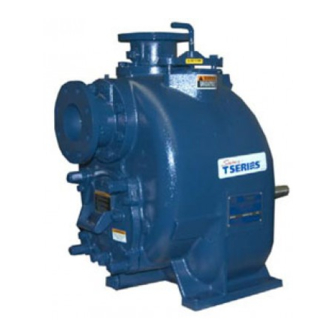
- Page 1 OM-05350-01 July 11, 2002 Rev. J 06‐20‐19 INSTALLATION, OPERATION, AND MAINTENANCE MANUAL WITH PARTS LIST SUPER T SERIES PUMPS MODELS T4A71S‐B INCLUDING: /F, /FM GORMAN‐RUPP PUMPS www.grpumps.com 2002 Gorman‐Rupp Pumps Printed in U.S.A.
- Page 2 Register your new Gorman‐Rupp pump online at www.grpumps.com Valid serial number and e‐mail address required. RECORD YOUR PUMP MODEL AND SERIAL NUMBER Please record your pump model and serial number in the spaces provided below. Your Gorman‐Rupp distributor needs this information when you require parts or service. Pump Model: Serial Number:...
-
Page 3: Table Of Contents
TABLE OF CONTENTS INTRODUCTION ..........PAGE I - 1 SAFETY - SECTION A . - Page 4 TABLE OF CONTENTS (continued) TROUBLESHOOTING - SECTION D ......PAGE D - 1 PREVENTIVE MAINTENANCE .
-
Page 5: Introduction
SUPER T SERIES OM-05350 INTRODUCTION Thank You for purchasing a Gorman‐Rupp pump. HAZARD AND INSTRUCTION Read this manual carefully to learn how to safely DEFINITIONS install and operate your pump. Failure to do so could result in personal injury or damage to the The following are used to alert maintenance per... -
Page 6: Safety - Section A
SUPER T SERIES OM-05350 SAFETY - SECTION A This information applies to Super T Se which may damage the pump or endan ries basic pumps. Gorman‐Rupp has no ger personnel as a result of pump fail control over or particular knowledge of ure. - Page 7 OM-05350 SUPER T SERIES are not observed. Make certain that these parts with great force when they hoists, chains, slings or cables are in are disengaged. Allow the pump to good working condition and of suffi completely cool before servicing it.
-
Page 8: Installation - Section B
SUPER T SERIES OM-05350 INSTALLATION - SECTION B Review all SAFETY information in Section A. specific application. Since the pressure supplied to the pump is critical to performance and safety, Since pump installations are seldom identical, this be sure to limit the incoming pressure to 50% of... -
Page 9: Preinstallation Inspection
OM-05350 SUPER T SERIES PREINSTALLATION INSPECTION POSITIONING PUMP Lifting The pump assembly was inspected and tested be fore shipment from the factory. Before installation, inspect the pump for damage which may have oc curred during shipment. Check as follows: a. Inspect the pump for cracks, dents, damaged Death or serious personal injury and threads, and other obvious damage. -
Page 10: Suction And Discharge Piping
SUPER T SERIES OM-05350 ches (267 mm) must be maintained to permit re these gauges are desired for pumps that are not moval of the cover. tapped, drill and tap the suction and discharge lines not less than 18 inches (457,2 mm) from the suction and discharge ports and install the lines. -
Page 11: Suction Lines In Sumps
OM-05350 SUPER T SERIES tight seal. Follow the sealant manufacturer's rec If two suction lines are installed in a single sump, ommendations when selecting and applying the the flow paths may interact, reducing the efficiency pipe dope. The pipe dope should be compatible of one or both pumps. -
Page 12: Discharge Lines
SUPER T SERIES OM-05350 In low discharge head applications (less than 30 DISCHARGE LINES feet or 9 meters), it is recommended that the by pass line be run back to the wet well, and located 6 Siphoning inches below the water level or cut‐off point of the low level pump. -
Page 13: Automatic Air Release Valve
OM-05350 SUPER T SERIES matic Air Release Valve will permit air to escape during operation. A closed manual shut‐ through the bypass line and then close automati off valve may cause a pump which has cally when the pump is fully primed and pumping lost prime to continue to operate with... -
Page 14: Alignment
SUPER T SERIES OM-05350 DISCHARGE PIPE CLEAN‐OUT COVER INSTALL AIR RELEASE VALVE IN HORIZONTAL POSITION DISCHARGE CHECK VALVE 90_ LONG RADIUS ELBOW SUPPORT PUMP DISCHARGE BRACKET SELF‐PRIMING CENTRIFUGAL PUMP BLEED LINE 1” (25,4 MM) DIA. MIN. (CUSTOMER FUR NISHED) DO NOT EX... -
Page 15: Coupled Drives
OM-05350 SUPER T SERIES Adjusting the alignment in one direction may alter the alignment in another direc tion. check each procedure after altering alignment. Coupled Drives Figure 5. Aligning Non‐Spider Type Couplings Check parallel adjustment by laying a straightedge across both coupling rims at the top, bottom, and When using couplings, the axis of the power side. -
Page 16: Drive Belt Tensioning
SUPER T SERIES OM-05350 Select pulleys that will match the proper speed ra DRIVE BELT TENSIONING tio; overspeeding the pump may damage both General Rules of Tensioning pump and power source. For new drive belts, check the tension after 5, 20 and 50 hours of operation and re‐tension as re... -
Page 17: Operation - Section C
OM-05350 SUPER T SERIES OPERATION - SECTION C Review all SAFETY information in Section A. Add liquid to the pump casing when: 1. The pump is being put into service for the Follow the instructions on all tags, labels and de... -
Page 18: Operation
OM-05350 SUPER T SERIES After the pump has been primed, partially close the dicated by the arrow on the pump body discharge line throttling valve in order to fill the line and on the accompanying decal. Other slowly and guard against excessive shock pres... -
Page 19: Strainer Check
OM-05350 SUPER T SERIES not, check for air leaks in the seal, gasket, or dis in the pump can reach boiling tempera charge valve. tures, and vapor pressure within the pump can cause parts being disen Open the suction line, and read the vacuum gauge gaged to be ejected with great force. -
Page 20: Bearing Temperature Check
OM-05350 SUPER T SERIES for approximately one minute; this will remove any Checking bearing temperatures by hand is inaccu remaining liquid that could freeze the pump rotat rate. Bearing temperatures can be measured ac ing parts. If the pump will be idle for more than a curately by placing a contact‐type thermometer... - Page 21 SUPER T SERIES OM-05350 TROUBLESHOOTING - SECTION D Review all SAFETY information in Section A. Before attempting to open or service the pump: 1. Familiarize yourself with this manual. 2. Lock out or disconnect the power source to ensure that the pump will remain inoperative.
- Page 22 OM-05350 SUPER T SERIES TROUBLE POSSIBLE CAUSE PROBABLE REMEDY Suction intake not submerged at Check installation and correct PUMP STOPS OR FAILS TO DELIVER proper level or sump too small. submergence as needed. RATED FLOW OR Impeller or other wearing parts worn Replace worn or damaged parts.
- Page 23 SUPER T SERIES OM-05350 equipped) between regularly scheduled inspec PREVENTIVE MAINTENANCE tions can indicate problems that can be corrected Since pump applications are seldom identical, and before system damage or catastrophic failure oc pump wear is directly affected by such things as curs.
- Page 24 OM-05350 SUPER T SERIES PUMP MAINTENANCE AND REPAIR - SECTION E MAINTENANCE AND REPAIR OF THE WEARING PARTS OF THE PUMP WILL MAINTAIN PEAK OPERATING PERFORMANCE. STANDARD PERFORMANCE FOR PUMP MODEL T4A71S‐B, Including /F, /FM Based on 70 F (21 C) clear water at sea level Contact the Gorman‐Rupp Company to verify per...
- Page 25 OM-05350 SUPER T SERIES ILLUSTRATION PARTS PAGE Figure 1. Pump Model T4A71S-B, Including /F, /FM PAGE E - 2 MAINTENANCE & REPAIR...
- Page 26 OM-05350 SUPER T SERIES PARTS LIST Pump Model T4A71S-B, Including /F, /FM (From S/N 1247200 Up) If your pump serial number is followed by an “N”, your pump is NOT a standard production model. Contact the Gorman‐Rupp Company to verify part numbers.
- Page 27 OM-05350 SUPER T SERIES ILLUSTRATION Figure 2. Repair Rotating Assembly PAGE E - 4 MAINTENANCE & REPAIR...
- Page 28 OM-05350 SUPER T SERIES PARTS LIST Repair Rotating Assembly ITEM PART NAME PART ITEM PART NAME PART NUMBER NUMBER IMPELLER 10528 1102H O‐RING S1674 SHIPPING PLUG 11495B 15079 CART SEAL ASSY 46513-151 ROT ASSY ADJ SHIM 13130-3 17040 /WWS MECH SEAL ASSY 12364D...
- Page 29 OM-05350 SUPER T SERIES to ensure that it will remain inoperative. Close all PUMP AND SEAL DISASSEMBLY valves in the suction and discharge lines. AND REASSEMBLY For power source disassembly and repair, consult Review all SAFETY information in Section A.
- Page 30 SUPER T SERIES OM-05350 Suction Check Valve Removal necessary and keep personnel away from suspended objects. (Figure 1) If the check valve assembly (28) is to be serviced, remove the check valve pin (29), reach through the back cover opening and pull the complete assem...
- Page 31 OM-05350 SUPER T SERIES longest length of pipe into the vent hole until fully Turn engaged. Install the tee, and screw the handles into Counterclockwise the tee. Use caution when lifting the rotating assem bly to avoid injury to personnel or damage to the as...
- Page 32 SUPER T SERIES OM-05350 assembly. Disassemble the shaft and bearings precautions printed on solvent contain only when there is evidence of wear or damage. ers. Clean the bearings thoroughly in fresh cleaning solvent. Dry the bearings with filtered compressed air and coat with light oil.
- Page 33 OM-05350 SUPER T SERIES Position the inboard oil seal (5A) in the bearing If heating the bearings is not practical, use a suit housing bore with the lip positioned as shown in ably sized sleeve, and an arbor (or hydraulic) press Figure 2.
- Page 34 SUPER T SERIES OM-05350 Seal Installation must be completely clean before installing the seal. (Figures 2, 5, 6 and 7) Most cleaning solvents are toxic and A new seal assembly should be installed flammable. Use them only in a well ven...
- Page 35 OM-05350 SUPER T SERIES shaft until it seats against the shaft shoulder. Re STATIONARY SEAT FULLY SEATED IN move the tape covering the threads. Check to en SEAL PLATE BORE sure that the shaft threads are free of any tape resi...
- Page 36 SUPER T SERIES OM-05350 Carefully wash all metallic parts in fresh cleaning to the shaft, making future removal difficult solvent and allow to dry thoroughly. or impossible without damage to the im peller or shaft. Install the same thickness of impeller adjusting shims (27) as previously removed.
- Page 37 OM-05350 SUPER T SERIES bly into the pump casing using the installation tool. wear plate and the impeller is .010 to .020 inch Be careful not to damage the O‐ring. (0,25 to 0,50 mm). Replace the back cover O‐rings (8A and 12A) and Install the same thickness of rotating assembly ad...
- Page 38 SUPER T SERIES OM-05350 turn the adjusting screws clockwise until the holes valve, apply `Loctite Pipe Sealant With Teflon No. in the locking collars realign with the tapped screw 592', or equivalent compound, on the relief valve holes in the back cover plate. Secure the locking threads.
- Page 39 OM-05350 SUPER T SERIES Bearings Power Source (Figure 2) Consult the literature supplied with the power The bearing housing was fully lubricated when source, or contact your local power source repre shipped from the factory. Check the oil level regu...
- Page 40 For Warranty Information, Please Visit www.grpumps.com/warranty or call: U.S.: 419-755-1280 Canada: 519-631-2870 International: +1-419-755-1352 GORMAN‐RUPP PUMPS...
Need help?
Do you have a question about the Super T Series and is the answer not in the manual?
Questions and answers