Advertisement
Quick Links
99cm
Imported by Amart Furniture Pty Ltd, Qld, Brisbane Australia.
For any assistance with assembly or for missing parts please phone
Amart Furniture, Customer Service Free call 1800 351 084
ASSEMBLY INSTRUCTION
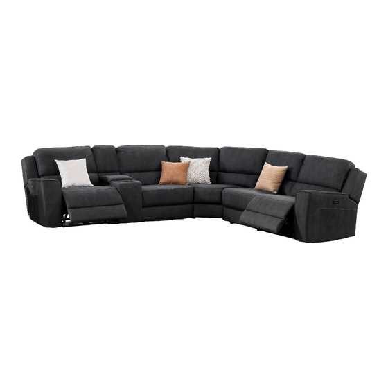
VIVALDI CORNER LOUNGE
ITEM CODE 68999
Imported by Amart Furniture Pty Ltd, Qld, Brisbane Australia.
For any assistance with assembly or for missing parts please phone
Amart Furniture, Customer Service Free call 1800 351 084
1
68999
Advertisement

Subscribe to Our Youtube Channel
Related Manuals for Amart Furniture VIVALDI 68999


Summary of Contents for Amart Furniture VIVALDI 68999
- Page 1 ASSEMBLY INSTRUCTION VIVALDI CORNER LOUNGE ITEM CODE 68999 Imported by Amart Furniture Pty Ltd, Qld, Brisbane Australia. For any assistance with assembly or for missing parts please phone Amart Furniture, Customer Service Free call 1800 351 084 99cm Imported by Amart Furniture Pty Ltd, Qld, Brisbane Australia. For any assistance with assembly or for missing parts please phone Amart Furniture, Customer Service Free call 1800 351 084 68999...
-
Page 2: Pre-Assembly Preparation
PRE‐ASSEMBLY PREPARATION Before you start: Choose a clean, level, spacious assembly area. Avoid hard surfaces that may damage the product Take care when lifting. Product should be assembled as near as possible to the point of use Ensure that you have all required contents for complete assembly Always read the assembly instructions carefully before beginning assembly. - Page 3 Step1: Locate power pack which is attached to the post at rear base of left hand facing electric seat. Step2: Slide back receivers into steel mechanism posts in the base of the left hand facing electric seat, and then press both sides of the back firmly into place to ensure the back automatically locks in place. Receiver at bottom of back rest Mechanism post at rear of seat slide receiver into post 68999...
- Page 4 Step3: Locate package of sofa legs that is placed into zipper pocket at the bottom of each armless chair, and 4 legs for each chair. With 2 people carefully turn onto back on piece of cardboard or carpet to protect covering Plastic leg a. Bolt M8X60 4pcs Step4: Take out the 4 plastic legs, then screw them into holes at the bottom of each armless chair. 68999...
- Page 5 Step5: Slide back receivers into steel mechanism posts in the base of each armless chair, and then press both sides of the back firmly into place to ensure the back automatically locks in place. Receiver at bottom of back rest Mechanism post at rear of seat slide receiver into post Step6: Locate package of sofa legs that is placed into zipper pocket at the bottom of corner piece. With 2 people carefully turn onto back on piece of cardboard or carpet to protect covering pocket Plastic leg a. Bolt M8X60 5pcs 68999...
- Page 6 Step7: Take out the 5 plastic legs, then screw them into holes at the bottom of corner piece. clockwise turning for tighten of the plastic leg with screw Step8: Slide back receivers into steel mechanism posts in the base of corner piece, and then press both sides of each back firmly into place to ensure each back automatically locks in place. Receiver at bottom of back rest Mechanism post at rear of seat slide receiver into post 68999...
- Page 7 Step9: Locate package of sofa legs that is placed into zipper pocket at the bottom of console. With 2 people carefully turn onto back on piece of cardboard or carpet to protect covering Plastic leg a. Bolt M8X60 4pcs Step10: Take out the 4 plastic legs, then screw them into holes at the bottom of console. 68999...
- Page 8 Step11: Locate power pack which is attached to the post at rear base of right hand facing electric seat. Step12: Slide back receivers into steel mechanism posts in the base of the right hand facing electric seat, and then press both sides of the back firmly into place to ensure the back automatically locks in place. Receiver at bottom of back rest Mechanism post at rear of seat slide receiver into post 68999...
- Page 9 Step13: Connect 6 pieces of corner from right to left. Begin with RHF facing electric recliner, then connect pieces as required until final item of LHF facing electric recliner. Right Left 1st PCS 6th PCS slide clips at connecting item into clips at connected item, then together press front and rear side of connecting item to ensure the clips go into each other to the bottom. Step14: Take out transformer cable, transformer and power cable from power pack taken from the post at rear base of left and right hand facing electric seat, and then connect. Transformer 68999...
-
Page 10: Safety Note
Step15: Plug transformer cables into sockets at back of the left and right hand facing electric seat in the same way. Safety Note: Transformer and cables are not to be placed under or within the recliner structure. transformer cable transformer power cable ASSEMBLY IS COMPLETE SAFETY NOTE: PLEASE ENSURE THAT ALL ELECTRICAL CORDS AND CABLES ARE CLEAR OF THE FRAME AND MECHANISM. A FAILURE TO DO SO MAY SEVER YOUR POWER CORD RESULTING IN SERIOUS INJURY OR DEATH. 68999... - Page 11 READ THESE INSTRUCTIONS THOROUGHLY BEFORE USE: DANGER: TO REDUCE THE RISK OF ELECTRIC SHOCK: Always unplug from electric outlet before cleaning. WARNING: RISK OF INJURY Keep children away from extended footrest and any moving parts. CAUTION: • Do not allow children to play on this electric recliner or operate the powered mechanism. The leg rest folds when closing and could possibly cause injury to a child.
- Page 12 68999...
Need help?
Do you have a question about the VIVALDI 68999 and is the answer not in the manual?
Questions and answers