
Related Manuals for Biomorph Level 3Plus


Summary of Contents for Biomorph Level 3Plus
- Page 1 Level 3Plus Ground Support Equipment (US) ltd., DBA Biomorph, 11 Broadway, New York, NY 10004. Tel and Fax 888 302 3375 info@biomorphdesk.com www.biomorph.com Copywright S.Barlow-Lawson 2022...
- Page 2 “Questions? Please call 917.328.8955 for support. IMPORTANT: Any issues at site must be reported to Biomorph immediately at 917 .328.8955, by text or phone and wait on site for response. Also, photos of completed desk(s) must be sent to 917 .328.8955 or vendors@biomorphdesk.com and wait ON SITE for approval. This will avoid potential revisits. Thank you.
-
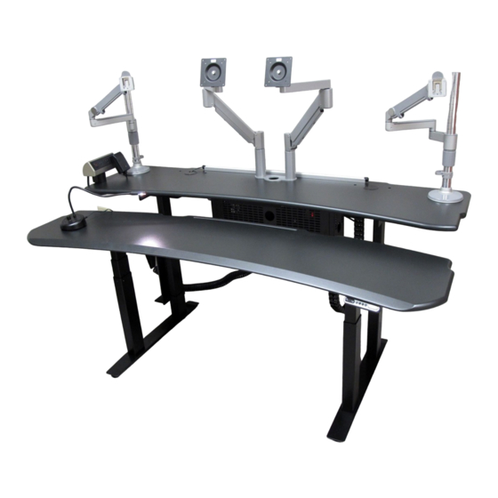
Page 3: Assembly Overview
Assembly Overview Assembly Overview IMPORTANT: DO NOT BUILD THIS TABLE UPSIDE DOWN. FRAME MUST BE BUILT RIGHT SIDE UP , IN PLACE, AND TOPS THEN ATTACHED. If this procedure is not followed then tops will not line up with frame. DO NOT REMOVE PROTECTIVE MATERIAL FROM TOPS UNTIL FINAL ASSEMBLY. - Page 4 Installing Leg-Mounted CPU Holder (optional) Place Leg (A) being installed in Step 3 into Shroud (e). Proceed to Step 4. Align CPU Holder with Shroud Slide CPU Support upward. Tighten screws using Allen and secure using four (4) M6 x Wrench.
-
Page 5: Leg Assembly
Leg Assembly M6 x 12 Screw Qty. 16 M6 x 12 Screw Qty. 16 Note: Longer end of Foot must face toward Glide front (user) side. Qty. 4... -
Page 6: Crossbar Assembly
Crossbar Assembly Note: This assembly is identical for 60” , 72” and 84” models. LH Side RH Side Use these holes. Use these holes. M6 x 12 Screw Qty. 8 LH Side RH Side Use these holes. Use these holes. - Page 7 Crossbar Assembly (continued) 60” LH Side 60” RH Side Use these holes. Use these holes. 72” LH Side 72” RH Side Use these holes. Use these holes. 84” LH Side 84” RH Side Use these holes. Use these holes. M6 Flange Head Nut Qty.
-
Page 8: Top Assembly
Top Assembly 5 x 25mm Wood Screw Qty. 62... -
Page 9: Electrical Components
Electrical Components 45˚ Digital Readout 16mm PH Switch and 45˚ Wood Screw Switch Bracket Qty. 2 Qty 1 45mm PH 4 Port Control Box Wood Screw Qty 1 Qty. 2... -
Page 10: Cable Management
Cable Management Cable Chains 16mm PH Qty 2 Wood Screw Qty. 4 Cable Cab 16mm PH Qty 1 Wood Screw Qty. 6... -
Page 11: Cable Diagram
Cable Diagram IMPORTANT: All cables must be tacked up and made neat with supplied cable guides. NO cables may hang down ex- cept those passing through cable chains. Make sure cables have enough slack between surfaces to allow full height adjustment between surfaces. IMPORTANT: Extend desktops to full opposite heights to ensure that cables will travel w/o stress). - Page 12 Questions? Call 888 302 3375 Operating your Biomorph Desk DPF1C control switch for Level Series, and Flexo DPF4T control switch for Plus Series Dual Drive Desks Series desks. DPF1C DPF4T May or may not have digital dispplay Toggle between surfaces Setting Initial Height.
-
Page 13: Troubleshooting Guide
Troubleshooting Guide QUESTIONS? PLEASE CALL TECH SUPPORT AT 917 328 8955 when you are in front of the For Biomorph Flexo, Level, and Plus Series Desks desk for real-time diagnosis. Flexo Series Level Series Plus Series Check for obstructions above, below and around the desk that may impede movement through the desk’s full...
Need help?
Do you have a question about the Level 3Plus and is the answer not in the manual?
Questions and answers