Table of Contents
Advertisement
Quick Links
BLACKMER TRUCK PUMPS
INSTALLATION OPERATION AND MAINTENANCE INSTRUCTIONS
Numbers in parentheses following individual parts
indicate reference numbers on Blackmer Parts Lists
101-D01 and 101-D02.
Blackmer pump manuals and parts lists may be
obtained from Blackmer's website (www.blackmer.com)
or by contacting Blackmer Customer Service.
This is a SAFETY ALERT SYMBOL.
When you see this symbol on the product, or in the
manual, look for one of the following signal words and be
alert to the potential for personal injury, death or major
property damage
Warns of hazards that WILL cause serious personal injury,
death or major property damage.
Warns of hazards that CAN cause serious personal injury,
death or major property damage.
Warns of hazards that CAN cause personal injury
or property damage.
NOTICE:
Indicates special instructions which are very
important and must be followed.
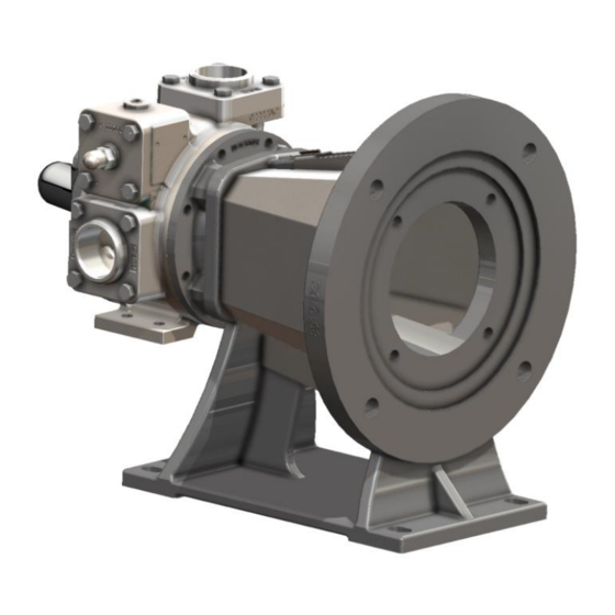
MODELS: X1220A & X1225A
TABLE OF CONTENTS
Technical Data ....................................................... 2
Initial Pump Start Up Information ........................... 2
Pre-Installation Cleaning ........................................ 3
Location and Piping ............................................... 3
Pump Drive ............................................................ 3
Pump Rotation ....................................................... 4
To Change Pump Rotation .................................... 4
Pre-Start Up Check List ......................................... 5
Start Up Procedures .............................................. 5
Pump Speed .......................................................... 5
Reverse Rotation ................................................... 5
Flushing the Pump ................................................. 6
Pump Relief Valve ................................................. 6
Relief Valve Setting and Adjustment ..................... 7
Strainers ................................................................ 7
Lubrication ............................................................. 7
Vane Replacement ................................................ 8
Pump Disassembly ................................................ 8
Pump Assembly ..................................................... 9
TROUBLE SHOOTING .....................................
SAFETY DATA
Blackmer Truck Pumps MUST only be installed in systems,
which have been designed by qualified engineering
personnel.
local and national regulations and safety standards.
This manual is intended to assist in the installation and
operation of the Blackmer truck pumps, and MUST be kept
with the pump.
Pump service shall be performed by qualified technicians
ONLY. Service shall conform to all applicable local and
national regulations and safety standards.
Thoroughly review this manual, all instructions and hazard
warnings, BEFORE performing any work on the pump.
Maintain ALL system and pump operation and hazard
warning decals.
961928
INSTRUCTIONS NO. 101-D00
Section
Effective
Replaces
NOTICE:
The system MUST conform to all applicable
101
Aug 2023
New
Page
11
Advertisement
Table of Contents

Subscribe to Our Youtube Channel
Related Manuals for BLACKMER X1220A


Summary of Contents for BLACKMER X1220A
-
Page 1: Table Of Contents
This manual is intended to assist in the installation and operation of the Blackmer truck pumps, and MUST be kept with the pump. Warns of hazards that WILL cause serious personal injury, Pump service shall be performed by qualified technicians death or major property damage. -
Page 2: Pump Data
A pump Identification tag, containing the pump serial number, I.D. number, and model designation, is attached to each pump. It is recommended that the data from this tag be recorded and filed for future reference. If replacement parts are needed, or if information pertaining to the pump is required, this data must be furnished to a Blackmer representative. TECHNICAL DATA... -
Page 3: Installation
INSTALLATION NOTICE: Install pressure gauges in the NPT ports provided in the Blackmer pumps must only be installed in systems pump casing to check pump performance at start up. designed by qualified engineering personnel. System ALL piping and fittings MUST be properly supported to design must conform with all applicable regulations and prevent any piping loads from being placed on the pump. -
Page 4: Pump Rotation
INSTALLATION CHECK VALVES The use of check valves or foot valves in the supply tank is not recommended with self-priming, positive displacement pumps. If the possibility of liquid backflow exists when the pump is off, a check valve in the pump discharge piping is recommended because the pump can motor in the reverse rotation and create undue stress on all attached components. -
Page 5: Operation
INSTALLATION Operation without guards in place can cause serious personal injury, major property damage, or death. Do not operate without guard in place PUMP ROTATION NOTICE: Confirm correct pump rotation by checking the pump rotation arrows respective to piping flow direction. Do not operate the pump in reverse rotation to reverse the direction of flow. -
Page 6: Start Up Procedures
OPERATION START UP PROCEDURES NOTICE: Consult the "General Pump Troubleshooting" section of this manual if difficulties during start up are experienced. Start the pump. Priming should occur within one minute. Check the vacuum and pressure gauges to ensure the pump is operating within the expected conditions. Inspect piping, fittings, and associated system equipment for leaks, noise, vibration and overheating. -
Page 7: Relief Valve Setting And Adjustment
Retighten the locknut DO NOT adjust the relief valve pressure setting while the Refer to Blackmer Pump Parts List 101-A01 for relief valve pump is in operation. spring pressure ranges. Unless specified otherwise, pumps are supplied from the factory with the relief valve adjusted to the mid-point of the spring range. -
Page 8: Vane Replacement
MAINTENANCE Bend up the engaged lockwasher tang and rotate VANE REPLACEMENT the locknut counterclockwise to remove it from the NOTICE: shaft. Maintenance shall be performed by qualified technicians Slide the lockwasher off the shaft. Inspect the only. Following the appropriate procedures and lockwasher for damage and replace as required. -
Page 9: Pump Assembly
MAINTENANCE PUMP ASSEMBLY 16. Install locknut (24A) onto threads of shaft with the Before reassembling the pump, inspect all component parts tapered end inward. for wear or damage, and replace as required. Wash out the 17. Tighten the locknut (24A) with a spanner wrench to pull bearing/seal recess of the head and cylinder and remove any the rotor flat against the back wall of the cylinder. - Page 10 MAINTENANCE the locknut. The pump should continue to turn freely 31. Install and finger tighten the head capscrews (21). The when rotated by hand. head capscrews will be fully tightened after the second locknut is installed. 44. To check adjustment, grasp the nut and washer with fingers and rotate back and forth.
- Page 11 PUMP TROUBLESHOOTING NOTICE: MAINTENANCE SHALL BE PERFORMED BY QUALIFIED TECHNICIANS ONLY, FOLLOWING THE APPROPRIATE PROCEDURES AND WARNINGS AS PRESENTED IN THIS MANUAL. SYMPTOM PROBABLE CAUSE 1. Pump not wetted. Pump Not Priming 2. Worn vanes. 3. Internal control valve closed. 4.
- Page 12 NOTES 101-A00 Page 12/14...
- Page 13 1809 Century Avenue, Grand Rapids, Michigan 49503-1530 U.S.A. Telephone: (616) 241-1611 • Fax: (616) 241-3752 E-mail: blackmer @blackmer.com • Internet Address: www .blackmer.com 101-A00 Page 13/14...
- Page 14 101-A00 Page 14/14...
Need help?
Do you have a question about the X1220A and is the answer not in the manual?
Questions and answers