Table of Contents
Advertisement
Quick Links
TID-0066_0B
TECHNICAL INSTRUCTIONS
24-Month Maintenance
Kit P/N 58025-05
For BMK1.5LN Boilers
Description of Document:
This TID provides the procedures to perform
recommended 24-Month maintenance on the
following Benchmark Low NOx Boiler Models:
• Benchmark 1.5LN
• Benchmark 1.5LN Dual-Fuel
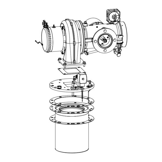
BMK 1.5LN Blower/Burner Assembly
Latest Update: 10/16/2014
AERCO International, Inc. • 100 Oritani Dr. • Blauvelt, New York 10913 • Phone: 800-526-0288
Advertisement
Table of Contents

Related Manuals for Watts AERCO 58025-05


Summary of Contents for Watts AERCO 58025-05
- Page 1 TID-0066_0B TECHNICAL INSTRUCTIONS 24-Month Maintenance Kit P/N 58025-05 For BMK1.5LN Boilers Description of Document: This TID provides the procedures to perform recommended 24-Month maintenance on the following Benchmark Low NOx Boiler Models: • Benchmark 1.5LN • Benchmark 1.5LN Dual-Fuel BMK 1.5LN Blower/Burner Assembly Latest Update: 10/16/2014 AERCO International, Inc.
-
Page 2: Table Of Contents
BMK1.5 LN Boiler 24-Month Maintenance Kit #58025-05 Instructions Technical Instruction Document TID-0066_0B TABLE OF CONTENTS INTRODUCTION ................3 CONTENTS OF 24-MONTH MAINTENANCE KIT ......3 TOOLS, TEST EQUIPMENT AND MATERIALS REQUIRED ....3 Tools ........................ 3 Test Equipment ....................4 Materials ...................... -
Page 3: Introduction
BMK1.5 LN Boiler 24-Month Maintenance Kit #58025-05 Instructions Technical Instruction Document TID-0066_0B INTRODUCTION This Technical Instruction Document (TID) provides the procedures to perform waterside and fireside inspections of the heat exchanger contained in Benchmark 1.5LN and 1.5LN Dual-Fuel boilers equipped with an Igniter-Injector. This kit provides the parts required to perform the waterside and fireside inspections on the Benchmark 1.5LN and Dual-Fuel Boilers. -
Page 4: Test Equipment
BMK1.5 LN Boiler 24-Month Maintenance Kit #58025-05 Instructions Technical Instruction Document TID-0066_0B 3.2 Test Equipment No test equipment is required to perform the 24-month inspections and maintenance included in these instructions. However, following completion of these inspections, the Benchmark Boiler should be tested using the combustion calibration procedures provided in O &... -
Page 5: Waterside Inspection Of The Heat Exchanger
BMK1.5 LN Boiler 24-Month Maintenance Kit #58025-05 Instructions Technical Instruction Document TID-0066_0B TOP PANEL 2 SIDE PANELS (EACH SIDE) Figure 1: Benchmark 1.5 Low NOx (LN) Boiler WATERSIDE INSPECTION OF THE HEAT EXCHANGER Benchmark 1.5LN Models contain a single heat exchanger, as shown in Figure 2. Perform the waterside inspection as follows: Burner Preliminary Disassembly and Inspection Instructions 1. - Page 6 BMK1.5 LN Boiler 24-Month Maintenance Kit #58025-05 Instructions Technical Instruction Document TID-0066_0B Figure 2: Benchmark 1.5LN - (Side View) Figure 3: Benchmark 1.5LN - (Rear View) AERCO International, Inc. • 100 Oritani Dr. • Blauvelt, New York 10913 • Phone: 800-526-0288 VD2: 10/14/14 Page 6 of 24...
-
Page 7: Fireside Inspections & Component Replacement
BMK1.5 LN Boiler 24-Month Maintenance Kit #58025-05 Instructions Technical Instruction Document TID-0066_0B FIRESIDE INSPECTIONS & COMPONENT REPLACEMENT The heat exchanger fireside inspection includes removal of the Burner and recommended replacement of Burner components and inspection of the Exhaust Manifold assembly and replacement of Condensate Trap components. - Page 8 BMK1.5 LN Boiler 24-Month Maintenance Kit #58025-05 Instructions Technical Instruction Document TID-0066_0B IGNITER- INJECTOR (P/N 66026) FLAME DETECTOR (P/N 66034) Figure 4: Benchmark 1.5LN - Top View AERCO International, Inc. • 100 Oritani Dr. • Blauvelt, New York 10913 • Phone: 800-526-0288 VD2: 10/14/14 Page 8 of 24...
- Page 9 BMK1.5 LN Boiler 24-Month Maintenance Kit #58025-05 Instructions Technical Instruction Document TID-0066_0B AIR/FUEL BLOWER PROOF SWITCH BLOWER VALVE BLOCKED INLET SWITCH A/F VALVE TO GAS TRAIN O-RING (P/N 88003) BLOWER GASKET HEX HEAD SCREWS (4) (P/N 81064) STAGED IGNITION SOLENOID BURNER PLATE GROUNDING SCREW FLAME DETECTOR (P/N 66034)
- Page 10 BMK1.5 LN Boiler 24-Month Maintenance Kit #58025-05 Instructions Technical Instruction Document TID-0066_0B 4. Refer to the partial exploded view in Figure 6. Using a 7/16” open-end wrench, disconnect the compression nut securing the Gas Injector Tube of the Igniter-Injector to the elbow of the Staged Ignition Assembly.
- Page 11 BMK1.5 LN Boiler 24-Month Maintenance Kit #58025-05 Instructions Technical Instruction Document TID-0066_0B IMPORTANT! There are some installations where it may be necessary to disassemble the Air/Fuel valve from the Blower to access the Burner. Note that there is a gasket located between the A/F Valve and Blower adapter (P/N 81057), as shown in Figure 7.
-
Page 12: Preliminary Burner Reassembly
BMK1.5 LN Boiler 24-Month Maintenance Kit #58025-05 Instructions Technical Instruction Document TID-0066_0B NOTE The Burner Plate is heavy, weighing approximately 20 pounds. 14. Remove the Burner Plate and then the Burner by pulling straight up. Do not scrape or bang the Burner Mesh during removal of the Burner. -
Page 13: Burner Component Replacement
BMK1.5 LN Boiler 24-Month Maintenance Kit #58025-05 Instructions Technical Instruction Document TID-0066_0B 5. To each of the eight (8) Burner mounting studs coming up through the Burner flange, add one of the 3/8” flat washers removed during disassembly. 6. After placing the washers, apply Loctite 246 to the Burner mounting studs. While supporting the housing so it is level with the Burner flange, use a torque wrench to tighten the eight (8) 3/8-16 hex nuts on the Burner flange to 35 ±... - Page 14 BMK1.5 LN Boiler 24-Month Maintenance Kit #58025-05 Instructions Technical Instruction Document TID-0066_0B NOTE The Igniter-Injector hardware contains a compression nut (P/N 56047) with a built-in ferrule and three clocking (indexing) washers (P/N 53033). These washers are used, as needed, to properly position the Igniter-Injector’s gas injector tube, as described in the following step.
-
Page 15: Final Burner Reassembly
BMK1.5 LN Boiler 24-Month Maintenance Kit #58025-05 Instructions Technical Instruction Document TID-0066_0B 6.1.4 Final Burner Reassembly After Burner component replacement (Section 6.1.3), continue Burner reassembly as follows: Final Burner Reassembly Instructions 1. Reinstall the grounding screw to the Burner Plate (Figure 4). 2. -
Page 16: Exhaust Manifold Reassembly
BMK1.5 LN Boiler 24-Month Maintenance Kit #58025-05 Instructions Technical Instruction Document TID-0066_0B Figure 9: Benchmark 1.5LN Exhaust Manifold Location – Right Side View 6.2.2 Exhaust Manifold Reassembly To reassemble the Exhaust Manifold: Exhaust Manifold Reassembly Instructions 1. Refer to Figure 10 and replace the exhaust manifold seal (part no. 84020) with the new seal provided in the 24-month maintenance kit. -
Page 17: Condensate Trap Component Replacement
BMK1.5 LN Boiler 24-Month Maintenance Kit #58025-05 Instructions Technical Instruction Document TID-0066_0B Figure 10: Benchmark 1.5LN Exhaust Manifold 6.2.3 Condensate Trap Component Replacement For Benchmark 2.0 boilers, the Condensate Trap (P/N 24060) is attached to the connecting manifold drain pipe using a special adapter (Figure 11). NOTE The Condensate Trap should already be disconnected from the Exhaust Manifold of the unit during the Exhaust Manifold... - Page 18 BMK1.5 LN Boiler 24-Month Maintenance Kit #58025-05 Instructions Technical Instruction Document TID-0066_0B This trap should be disconnected from the connecting manifold and serviced as follows: Condensate Trap Component Replacement Instructions 1. Remove the connections on the inlet and outlet sides of the Condensate Trap shown in Figure 12.
- Page 19 BMK1.5 LN Boiler 24-Month Maintenance Kit #58025-05 Instructions Technical Instruction Document TID-0066_0B Figure 11: Condensate Trap P/N 24060 (Old and New Styles) Figure 12: Exhaust Manifold Condensate Drain Location. Old (left) and New (right) Style Trap - BMK1.5LN Partial Left Side View AERCO International, Inc.
-
Page 20: Replacing The Lwco Probe/Capacitor Assembly
BMK1.5 LN Boiler 24-Month Maintenance Kit #58025-05 Instructions Technical Instruction Document TID-0066_0B 6.3 Replacing the LWCO Probe/Capacitor Assembly The replacement LWCO probe sensor comes with a capacitor assembly attached. This procedure replaces an old probe assembly with a new probe assembly (P/N 69126). Replacing the LWCO Probe/Capacitor Assembly Cut the shell harness wire just below the female spade connector (Figure 13). - Page 21 BMK1.5 LN Boiler 24-Month Maintenance Kit #58025-05 Instructions Technical Instruction Document TID-0066_0B 6.3.1.1 Low Water Cutoff (LWCO) - Capacitor Electrical Short Test This test determines if there is an electrical short between the LWCO capacitor and the heat exchanger. Perform the capacitor electrical short test as described below. LWCO Capacitor Electrical Short Test 1.
- Page 22 BMK1.5 LN Boiler 24-Month Maintenance Kit #58025-05 Instructions Technical Instruction Document TID-0066_0B Connect 1 Lead to LWCO Terminal Connect 2 Lead to PIN #6 Ohmmeter 19-Pin Shell Harness Cable Connector LWCO Probe Assembly Connector Figure 15: Connecting Ohmmeter Between LWCO Probe & Shell Harness Cable 5.
-
Page 23: Final Reassembly And Testing
BMK1.5 LN Boiler 24-Month Maintenance Kit #58025-05 Instructions Technical Instruction Document TID-0066_0B FINAL REASSEMBLY AND TESTING Upon completion of all inspections and component replacement, reassemble the unit and perform the tests specified in paragraphs 7.1 and 7.2. 7.1 Set-Up and Reassembly After Maintenance Following completion of the all required inspections and replacements, perform the following reassembly and setup procedures: Setup and Reassembly After Maintenance Instructions... - Page 24 BMK1.5 LN Boiler 24-Month Maintenance Kit #58025-05 Instructions Technical Instruction Document TID-0066_0B Change Log Date Description Changed By 07/09/2012 Rev A: Initial release Chris Blair Rev B: 1028-5: Replaced Flame Detector 66020 with 66034. Added new step 7 Chris Blair 10/16/2014 to section 6.1.1 to replace Plug Gasket (P/N 81129) 934-99: Added section 6.3, replacing the LWCO...
Need help?
Do you have a question about the AERCO 58025-05 and is the answer not in the manual?
Questions and answers