Milesight UC50 Series User Manual
Multi-interface controller, lte version
Hide thumbs
Also See for UC50 Series:
- User manual (37 pages) ,
- User manual (25 pages) ,
- User manual (28 pages)
Table of Contents
Advertisement
Quick Links
Advertisement
Table of Contents

Subscribe to Our Youtube Channel
Related Manuals for Milesight UC50 Series


Summary of Contents for Milesight UC50 Series
- Page 1 Multi-interface Controller UC50x Series (LTE Version) User Guide...
- Page 2 Safety Precautions Milesight will not shoulder responsibility for any loss or damage resulting from not following the instructions of this operating guide. The device must not be remodeled in any way. Do not place the device close to objects with naked flames.
- Page 3 Revision History Date Doc Version Description Mar. 30, 2024 V 1.0 Initial version...
-
Page 4: Table Of Contents
Contents 1. Product Introduction ......................... 5 1.1 Overview ...........................5 1.2 Features ........................... 5 2. Hardware Introduction ........................5 2.1 Packing List ..........................5 2.2 Hardware Overview ......................... 6 2.3 Internal Interfaces ........................7 2.4 Dimensions (mm) ........................7 3. Hardware Adjustment ........................7 3.1 SIM Installation ........................8 3.2 Hardware Switch ........................ -
Page 5: Product Introduction
1. Product Introduction 1.1 Overview UC50x series is a multi-interface controller used for data acquisition from multiple sensors. It contains different I/O interfaces such as analog inputs, digital inputs, digital outputs, serial ports and so on, which simplify the deployment and replacement of cellular networks. UC50x series can be easily and quickly configured by NFC. -
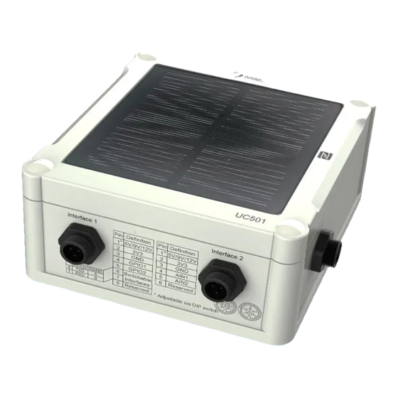
Page 6: Hardware Overview
2.2 Hardware Overview UC501 UC502 Data Interface 1: Description 5V/9V/12V OUT (Switchable) 3.3V OUT Analog Input 1 Analog Input 2 5-24V DC IN ①② Data Interface 2: Description 5V/9V/12V OUT (Switchable) 3.3V OUT GPIO1 GPIO2 RS232/RS485 (Switchable) SDI-12 RS232 RS485 When both DC external power and batteries are connected, external power will be the preferred power supply ①... -
Page 7: Internal Interfaces
2.3 Internal Interfaces Power Button: Function Action LED Indication Turn On Press and hold the button for more than 3s. Off → Turn Off Press and hold the button for more than 3s. → Off Reset Press and hold the button for more than 10s. Blinks. -
Page 8: Sim Installation
3.1 SIM Installation Release the screw caps, screws and back cover to insert the SIM card (3FF). Note: The device does not support hot plugging (also called hot swapping), please reboot the device after inserting the SIM card. 3.2 Hardware Switch The default work mode of analog input is 4-20mA, and the default voltage of power output is 12V. -
Page 9: Back Cover Restore
Note: Power output on interface 1 is used for powering analog devices, power output on interface 2 is used for powering serial port devices and SDI-12 devices. 3.3 Back Cover Restore Please follow the instructions below to screw the back cover to ensure the waterproof of the device. -
Page 10: Communication Settings
1. Download and install Milesight ToolBox App from Google Play or Apple App Store. 2. Enable NFC on the smart phone and launch Milesight ToolBox. 3. Attach the smart phone with NFC area to the device, click NFC read to read device information. -
Page 11: Application Mode Settings
Parameters Description The Access Point Name for dialing up network connection provided by local ISP. The max length is 31 characters. Authentication NONE, PAP and CHAP are optional. Type Network Type Select network type according to device model. The username for dialing up network connection provided by local ISP. The Username max length is 31 characters. - Page 12 Parameters Description Select from AWS, TCP, UDP, and MQTT. Application Mode Note: when the mode is TCP or UDP, RS232/RS485 Transparent/SDI-12 Transparent will not follow these settings. Keepalive Interval After being connected to the server, the device will send a heartbeat packet regularly to keep alive.
- Page 13 Import the client key. Client Key TCP/UDP When TCP connection fails, the device will reconnect to the server at the Reconnection preset interval. Interval(s) When TCP heartbeat times run out, the device will resend heartbeat. After it Number of reaches the preset number of reconnections, the device will reconnect to TCP Reconnections server.
-
Page 14: Interface Settings
SDI-12 Customize the uplink or downlink topic when SDI-12 Transparent mode is Pass-through enabled. Uplink/Dowlink Topic QoS 0 – Only Once This is the fastest method and requires only 1 message. It is also the most unreliable transfer mode. QoS 1 – At Least Once This level guarantees that the message will be delivered at least once, but may be delivered more than once. - Page 15 Parameters Description Reporting interval of transmitting data to server. Default: 360 mins, Range: Reporting 1-1440 mins. Interval Note: RS232 transmission will not follow the reporting interval. Collection The interval of collecting data when there is an alarm command. This Interval interval must be not more than reporting interval.
-
Page 16: Analog Input
reduce battery life. Data Storage Disable or enable reporting data storage locally. When the device detects the server disconnection and re-connection, it will send the data including disconnection time. Note: 1) If the device is rebooted or powered off during data retransmission and the process is not completed, the device will resend all retransmitted data Data again after reconnecting to the network. - Page 17 Parameters Description Enable 5V/9V/12V power output of interface 1 to supply power to analog devices. It’s 12V by default and you can change DIP switches to change Interface 1(Pin 1) voltage. 5V/9V/12V Output Power Output Time Before Collect: power supply time before collecting data for terminal device initialization.
-
Page 18: Rs485
Unit The data unit of this sensor, it just displays on ToolBox for reference. Fetch Click to fetch current value of sensor. Note: analog input scaling formula Ov = [(Osh - Osl) * (Iv - Isl) / (Ish - Isl)] + Osl This can also be rewritten as: Ov = [(Osh - Osl)/(lsh - lsl)/(lsh - lsl)] + Osl The variables are pertinent to the scaling formula:... - Page 19 Parameters Description Enable 5V/9V/12V power output of interface 2 to supply power to RS485 terminal devices. It’s 12V by default and you can change DIP switches Interface 2(Pin 1) change voltage. 5V/9V/12V Output Power Output Time Before Collect: power supply time before collecting data for terminal device initialization.
- Page 20 Parity None, Odd and Oven are available. Execution Interval The execution interval between each Modbus command. The maximum response time that the UC50x waits for the reply to the Max Resp Time command. If it does not get a response after the max response time, it is determined that the command has timed out.
- Page 21 Parameters Description Channel ID Select the channel ID you want to configure from 16 channels. Name Customize the name to identify every Modbus channel. Slave ID Set Modbus slave ID of terminal device. Address The starting address for reading. Quantity Set read how many digits from starting address.
- Page 22 After clicking, the device will send Modbus read command to test if it can read correct values. Collect Example: as above setting, the device will send command: 01 03 00 00 00 01 84 0A Fetch Click to check the collected data. Active Transparent: The server can send any command to the RS485 device and the RS485 device can only react according to server commands.
-
Page 23: Rs232
Group Server Address Fill in the TCP or UDP server address (IP/domain name). Port Fill in the TCP or UDP server port. Range: 1-65535. Network Status Show the connection status between the device and the server. 4.3.4 RS232 When work mode is low power mode, the device can forward RS232 data to server and is not able to receive the downlink commands from the server immediately. - Page 24 Parameters Description Baud Rate 300/1200/2400/4800/9600/19200/38400/57600/115200 are available. Data Bit 8 bit is available. Stop Bit 1 bit/2 bit are available. Parity None, Odd and Oven are available. Packet Length When the device receives RS232 data up to this length, it will fragment it as (byte) a single packet and send to server.
-
Page 25: Gpio
Serial Port Frame When the device receives serial data up to this length, it will fragment it as a Length (byte) single packet and send to server. The interval that the device sends out real serial data stored in the buffer Serial Port Frame area to public network. - Page 26 Initial status of digital input. Digital Input Pull Down: rising edge will be triggered Pull Up/None: falling edge will be triggered Fetch Click to get current status of digital input. Digital Output: Digital output will send voltage signals to control devices. Parameters Description Fetch...
-
Page 27: Sdi-12
Pull Down: Increase 1 when detecting rising edge Pull Up/None: Increase 1 when detecting falling edge Digital Filter It’s recommended to enable when pulse period is greater than 250 us. Make the device start/stop counting. Start/Stop Note: UC50x will send non-changable counting values if you do not click Start. - Page 28 Parameters Description Enable 5V/9V/12V power output of interface 2 to supply power to SDI-12 sensors. It’s 12V by default and you can change DIP switches to change Interface 2(Pin 1) voltage. 5V/9V/12V Output Power Output Time Before Collect: power supply time before collecting data for terminal device initialization.
- Page 29 Passthrough Uplink/Downlink Topics. TCP/UDP Keepalive After being connected to TCP server, the device will send a heartbeat packet by TCP regularly to keep alive. Interval(s) Reconnection When TCP connection fails, the device will reconnect to the server at the Interval (s) preset interval.
-
Page 30: Alarm Settings
Parameters Description Channel ID Select the channel ID you want to configure from 16 channels. Name Customize the name of each channel to easily identify them. Address Address of SDI-12 sensor, it is editable. Write Click to modify a new address to SDI-12 sensor. Fill in the commands to send to sensors, one channel can add 16 SDI-12 Command commands at most. -
Page 31: Data Storage
2. Set an IF condition including the analog input values or RS485 Modbus channel values. When the value matches the condition, the device will report an alarm packet. Note: the device will only send the alarm once. Only when the value turns back to normal and triggers the condition again, it will send a new alarm. - Page 32 automatically or ToolBox App manually. 2. Go to Device > Settings > General Settings of ToolBox App to enable data storage feature. 3. Go to Device > Maintenance of ToolBox App, click Export, then select the data time range and click Save to export data.
-
Page 33: Maintenance
4.6 Maintenance 4.6.1 Upgrade 1. Download firmware from Milesight official website to your smart phone. 2. Open ToolBox App and click Browse to import firmware and upgrade the device. Note: 1) Operation on ToolBox is not supported during the upgrade. -
Page 34: Reset To Factory Default
4.6.3 Reset to Factory Default Please select one of following methods to reset device: Via Hardware: Open the case of UC50x and hold on power button more than 10s. Via ToolBox App: Go to Device > Maintenance to click Restore Factory Settings, then attach smart phone with NFC area to UC50x to complete reset. -
Page 35: Installation
It’s necessary to fix this bracket to device, or it will affect the signal. 6. Device Payload Please refer to the UC50x Series (LTE Version) Communication Protocol ; for decoders of Milesight IoT products please click here. -END-...
Need help?
Do you have a question about the UC50 Series and is the answer not in the manual?
Questions and answers