Table of Contents
Advertisement
Quick Links
*Q104SD SERIES
INSTALLATION INSTRUCTIONS
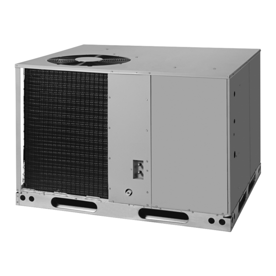
SINGLE PACKAGE HEAT PUMP - SINGLE PHASE - R410A
It is your responsibility to know this product better than your customer. This includes being
able to install the product according to strict safety guidelines and instructing the customer on
how to operate and maintain the equipment for the life of the product. Safety should always be
the deciding factor when installing this product and using common sense plays an important
role as well. Pay attention to all safety warnings and any other special notes highlighted in the
manual. Improper installation of the furnace or failure to follow safety warnings could result in
serious injury, death, or property damage.
These instructions are primarily intended to assist qualified individuals experienced in the
proper installation of this appliance. Some local codes require licensed installation/service
personnel for this type of equipment. Please read all instructions carefully before starting the
installation. Return these instructions to the customer's package for future reference.
DO NOT DESTROY. PLEASE READ CAREFULLY & KEEP IN A SAFE PLACE FOR FUTURE REFERENCE.
IMPORTANT
ATTENTION INSTALLERS:
13.4 SEER2 / 6.7 HSPF2
Advertisement
Table of Contents

Related Manuals for Nortek VQ104SD


Summary of Contents for Nortek VQ104SD
- Page 1 *Q104SD SERIES 13.4 SEER2 / 6.7 HSPF2 INSTALLATION INSTRUCTIONS SINGLE PACKAGE HEAT PUMP - SINGLE PHASE - R410A IMPORTANT ATTENTION INSTALLERS: It is your responsibility to know this product better than your customer. This includes being able to install the product according to strict safety guidelines and instructing the customer on how to operate and maintain the equipment for the life of the product.
-
Page 2: Table Of Contents
INSTALLER INFORMATION IMPORTANT SAFETY INFORMATION ....3 REFRIGERANT CHARGING ........9 Charging an R-410A Unit in AC Mode ....10 GENERAL INFORMATION ........4 Charging an R-410A Unit in Heating Mode ...10 Before you install this unit ........4 Verification of Charge in Refrigerant Heating Locating the Heat Pump ........4 Mode ..............10 Field Connections for Electrical Power Supply ..4... -
Page 3: Important Safety Information
INSTALLER INFORMATION IMPORTANT SAFETY INFORMATION WARNING: Safety markings are used frequently throughout this manual to designate a degree or level of seriousness and Do not place combustible material on or against should not be ignored. WARNING indicates a potentially the unit cabinet. Do not place combustible hazardous situation that if not avoided, could result in materials, including gasoline and any other personal injury or death. -
Page 4: General Information
GENERAL INFORMATION The Q104SD series heat pump is designed only for 0" 36” For Coil Only outdoor rooftop or ground level installations. This unit has been tested for capacity and efficiency in accordance with AHRI Standards and will provide many years of safe and dependable comfort, providing it is properly installed and maintained. -
Page 5: Air Filter Requirements
• Single phase downflow applications require either a Minimum Clearances Nortek internal filter kit be used, or an air filter system Q104SD units are certified as combination heating and be installed in the return air ductwork. See Table 2 for cooling equipment for outdoor installation only. -
Page 6: Rooftop
Condensate Drain Roof Curb Figure 4. Condensate Drain Location Figure 3. Roof Top Installation ELECTRICAL WIRING • A suitable mounting pad must be provided and separate WARNING: from the building foundation. The pad must be level to ensure proper condensate disposal and strong enough To avoid risk of electrical shock, personal injury, to support the unit’s weight. -
Page 7: Grounding
Safety Protection or circuit breaker for the unit. Incoming field wiring • A high-pressure switch is factory-installed and located and minimum size of electrical conductors and circuit in the compressor discharge line of the unit. The switch protection must be in compliance with information listed is designed to de-energize the system when very high on the outdoor unit data label. -
Page 8: Ambient Sensor Mounting
Forced Defrost When the Following Conditions are Met: • LPS and HPS are closed • Y1 input is active • O input is either active or inactive Bolt • TEST terminals shorted for more than three seconds Compressor will start and unit will operate in DEFROST mode. -
Page 9: Start Up & Adjustments
START UP & ADJUSTMENTS 2. Feel the air being circulated by the indoor blower and verify that it is cooler than ambient temperature. Pre-Start Check List Listen for any unusual noises. If unusual sounds occur, √ Verify the unit is level and allows condensate to drain. determine the source of the noise and correct as √... -
Page 10: Charging An R-410A Unit In Ac Mode
IMPORTANT NOTES: • Return to the system when the outdoor temperature • To achieve rated capacity and efficiency the compressor is 60 degrees F or higher and follow the steps defined must be exposed to refrigerant for at least 24 hours in Charging an R410A Unit in AC Mode. -
Page 11: Figures & Tables
FIGURES & TABLES 24.9 .75" NPT Female Drain Connector DOWNFLOW SUPPLY DUCT OPENING Top View 47.5 13.5 13.5 13.3 23.5 DOWNFLOW RETURN DUCT OPENING HORIZONTAL SUPPLY DUCT CONDENSING OPENING HORIZONTAL COIL RETURN DUCT OPENING 13.5 Back View 16.0 13.5 16.0 13.7 12.45 1 4/5... -
Page 12: Electrical Information
Electrical Information to Blower Relay (Cooling Speed) Brown Y1- IN Orange Defrost Board W2 Out Accesory Heat W2 IN Plug Y2 IN (Not Used) L-24V Output Fault Monitor (See thermostat manual for compatibility) Indoor Unit Terminal Thermostat Block Sub-Base Typical Wiring (Field Supplied) for 1-Stage Heat Pump Heat/Cool, 1-Stage Electric Heat to Blower Relay (Cooling Speed) Brown Y1- IN... - Page 13 Figure 8. Wiring Diagram for 208/230V Units...
-
Page 14: Charging Charts - Cooling
Charging Charts - Cooling Figure 9. Charging Chart for 2 Ton Units Figure 10. Charging Chart for 2.5 Ton Units... - Page 15 Figure 11. Charging Chart for 3 Ton Units Figure 12. Charging Chart for 3.5 Ton Units...
- Page 16 Figure 13. Charging Chart for 4 Ton Units Figure 14. Charging Chart for 5 Ton Units...
-
Page 17: Airflow Data
Airflow Data EXTERNAL STATIC PRESSURE DROP - INCHES WATER COLUMN MODEL NUMBER Q104SD- Tap T1 38.4 40.3 44.4 48.9 54.5 62.0 72.5 Tap T2 32.6 34.2 36.5 39.5 44.1 48.5 53.5 60.5 Tap T3** 1070 29.6 1010 31.3 9456 33.4 34.9 38.8 42.5... -
Page 20: Installation Checklist
• Blower Assembly • Fan Grille • Cabinet Panels • Filter/Driers • Expansion Valves Specifications & illustrations subject to change without notice or incurring obligations (09/22). 1041473A O’Fallon, MO, © Nortek Global HVAC LLC 2022. All Rights Reserved. (Replaces 10414730)
Need help?
Do you have a question about the VQ104SD and is the answer not in the manual?
Questions and answers