Table of Contents
Advertisement
Quick Links
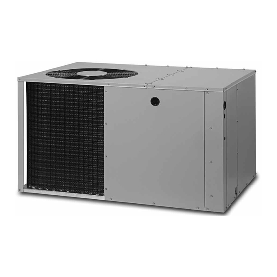
*Q7RE SERIES
INSTALLATION INSTRUCTIONS
Single Package Heat Pump - Single Stage, R-410A
It is your responsibility to know this product better than your customer. This includes being
able to install the product according to strict safety guidelines and instructing the customer on
how to operate and maintain the equipment for the life of the product. Safety should always be
the deciding factor when installing this product and using common sense plays an important
role as well. Pay attention to all safety warnings and any other special notes highlighted in the
manual. Improper installation of the furnace or failure to follow safety warnings could result in
serious injury, death, or property damage.
These instructions are primarily intended to assist qualified individuals experienced in the proper
installation of this appliance. Some local codes require licensed installation/service personnel
for this type of equipment. Please read all instructions carefully before starting the installation.
Return these instructions to the customer's package for future reference.
DO NOT DESTROY. PLEASE READ CAREFULLY & KEEP IN A SAFE PLACE FOR FUTURE REFERENCE.
IMPORTANT
ATTENTION INSTALLERS:
14 SEER
Advertisement
Table of Contents

Related Manuals for Nortek RQ7RE


Summary of Contents for Nortek RQ7RE
- Page 1 *Q7RE SERIES 14 SEER INSTALLATION INSTRUCTIONS Single Package Heat Pump - Single Stage, R-410A IMPORTANT ATTENTION INSTALLERS: It is your responsibility to know this product better than your customer. This includes being able to install the product according to strict safety guidelines and instructing the customer on how to operate and maintain the equipment for the life of the product.
-
Page 2: Table Of Contents
TABLE OF CONTENTS IMPORTANT SAFETY INFORMATION .....3 STARTUP & ADJUSTMENTS ........10 Pre-Start Checklist ..........10 REQUIREMENTS & CODES ........4 Start-Up Procedure ..........10 GENERAL INFORMATION ........4 Air Circulation ............10 Before You Install this Unit ........4 System Heating ............10 Locating the Heat Pump ..........4 System Cooling ............10 Minimum Clearances ..........4 Short Cycle Protection .........10... -
Page 3: Important Safety Information
IMPORTANT SAFETY INFORMATION WARNING: Please read all instructions before servicing this equipment. Pay attention to all safety warnings and any other special notes PROPOSITION 65 WARNING: This product highlighted in the manual. Safety markings are used frequently contains fiberglass wool, a product known to the throughout this manual to designate a degree or level of state of California to cause cancer. -
Page 4: Requirements & Codes
REQUIREMENTS & CODES area where they will be shaded from the afternoon sun, when the heat load is greatest. • All electrical wiring must be completed in accordance with • Consideration should also be given to availability of electric local, state & national codes and regulations and with the power, service access, noise, and shade. -
Page 5: Air Duct System
Air Duct System HEAT PUMP INSTALLATION Air ducts should be installed in accordance with the standards of Unpacking the Unit the National Fire Protection Association “Standard for Installation It is recommended that the unit be unpacked at the installation of Air Conditioning and Ventilation Systems” (NFPA 90A), site to minimize damage due to handling. -
Page 6: Return Duct
2. After measuring the return air box (approximately 12-1/4” x 20-1/4”), cut the hole through the floor so that the box will fit between the floor joists. Care should be taken when cutting through carpeting to avoid snags. NOTE: In most installations it will be necessary to cut a similar hole in the fiberboard directly under the hole in the floor. -
Page 7: Condensate Drainage
ELECTRICAL CONNECTIONS Condensate Drainage A 3/4” condensate fitting extends out of the side of the unit as shown in Figure 6. The drain trap, shipped in the electrical WARNING: compartment, must be installed to prevent water from collecting inside the unit. To avoid electric shock, personal injury, or death, 1. -
Page 8: Grounding
fuse or breaker for any heat pump is the smallest size that will the heater kit according to the to the installation instructions permit the equipment to run under normal usage and provide provided with the kit. maximum equipment protection. Properly sized fuses and •... -
Page 9: Ambient Sensor Mounting
HEAT RISE DATA (BASED ON NOMINAL 10KW ELECTRIC HEAT KIT) EXTERNAL STATIC PRESSURE DROP - INCHES WATER COLUMN MODEL BLOWER NUMBER SETTING HEAT HEAT HEAT HEAT HEAT HEAT HEAT HEAT RISE RISE RISE RISE RISE RISE RISE RISE Tap T1* Tap T2 1158 1119... -
Page 10: Startup & Adjustments
Air Circulation STATUS STATUS DIAGNOSTIC Leave the thermostat system mode on OFF, and set the fan INDICATOR TYPE DESCRIPTION mode to ON. Blower should run continuously. Check the air Operating Status Cooling, 1st Stage delivery at the supply registers and adjust register openings for Operating Status Heating, 1st Stage balanced air distribution. -
Page 11: Unit Maintenance
COMPONENT FUNCTIONS CAUTION: Low Pressure Switch (Select Models) - This safety switch is factory installed and located in the suction line internal to the The unit should never be operated without a unit. The switch is designed to protect the compressor if a loss filter in the return air system. -
Page 12: Refrigerant Charging Tables - Cooling
Refrigerant Charging Tables - Cooling NOTES: LEGEND Shaded boxes indicate flooded conditions. 1. All pressures are listed psig and all temperatures in °F Rated design values. The suction pressure will vary 2. Discharge temperatures greater than charted values indicate from design value if outdoor air flow, entering dry bulb, an undercharged system. - Page 13 LEGEND NOTES: Shaded boxes indicate flooded conditions. 1. All pressures are listed psig and all temperatures in °F Rated design values. The suction pressure will vary 2. Discharge temperatures greater than charted values indicate from design value if outdoor air flow, entering dry bulb, an undercharged system.
- Page 14 LEGEND NOTES: Shaded boxes indicate flooded conditions. 1. All pressures are listed psig and all temperatures in °F Rated design values. The suction pressure will vary 2. Discharge temperatures greater than charted values indicate from design value if outdoor air flow, entering dry bulb, an undercharged system.
-
Page 15: Refrigerant Charging Tables - Heating
Refrigerant Charging Tables - Heating LEGEND NOTE: Shaded boxes indicate flooded conditions. • All pressures are listed psig and all temperatures in °F Rated design values. 024K SERIES OUTDOOR TEMPERATURE (° F) Table 9. Charging Table for 2 Ton Models 030K SERIES OUTDOOR TEMPERATURE (°... - Page 16 LEGEND NOTE: Shaded boxes indicate flooded conditions. • All pressures are listed psig and all temperatures in °F Rated design values. 042K SERIES OUTDOOR TEMPERATURE (°. F) Table 12. Charging Table for 3.5 Ton Models 048K SERIES OUTDOOR TEMPERATURE (° F) Table 13.
-
Page 17: Figures & Tables
FIGURES & TABLES Top View 1.75 Ø Electric Heater Power Supply 1.125 Ø Power Supply 0.875 Ø Low Voltage Supply Side View Control Blower Access Panel Access 17.86 Panel 15.36 10.10 1" 3/4" NPT Drain Connection 1.38 18.01 3” 3.2 5.29 12.13 Opening for Alternate Power... -
Page 18: Wiring Diagrams
Wiring Diagrams Figure 10. W.D. for 2 & 2.5 Ton Models... - Page 19 Figure 11. W.D. for 3, 3.5 & 4 Ton Models...
- Page 20 Figure 12. W.D. for 5 Ton Models...
- Page 21 Typical Wiring for 1-Stage Cool / Heat, 1 Stage Electric Heat For HUD applications Remove white wire between terminal W2 INDOOR and W2 IN terminal TERMINAL *HUD DEFROST Outdoor BOARD Thermostat BROWN ORANGE JUMPER W2 IN W2 OUT For HUD applications move the white jumper wire from W2 terminal and connect to W2 IN terminal ACCESSORY HEAT PLUG...
-
Page 24: Installation Checklist
Failure to confirm proper charge and airflow may reduce energy efficiency and shorten equipment life. Specifications & illustrations subject to change without notice or incurring obligations (02/19). 1021569A O’Fallon, MO, © Nortek Global HVAC LLC 2019. All Rights Reserved. (Replaces 10215690)
Need help?
Do you have a question about the RQ7RE and is the answer not in the manual?
Questions and answers