Table of Contents
Advertisement
Quick Links
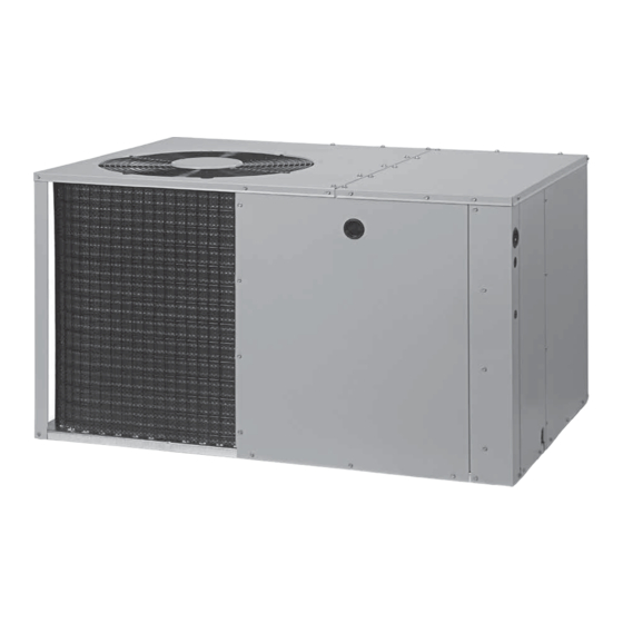
*Q7RE / PPH3RE SERIES
InStAllAtIon InStRuctIonS
Single Package Heat Pump - Single Stage, R-410A
It is your responsibility to know this product better than your customer. this includes being
able to install the product according to strict safety guidelines and instructing the customer on
how to operate and maintain the equipment for the life of the product. Safety should always be
the deciding factor when installing this product and using common sense plays an important
role as well. Pay attention to all safety warnings and any other special notes highlighted in the
manual. Improper installation of the furnace or failure to follow safety warnings could result in
serious injury, death, or property damage.
these instructions are primarily intended to assist qualified individuals experienced in the proper
installation of this appliance. Some local codes require licensed installation/service personnel
for this type of equipment. Please read all instructions carefully before starting the installation.
Return these instructions to the customer's package for future reference.
Do not DEStRoY. PlEASE READ cAREFullY & KEEP In A SAFE PlAcE FoR FutuRE REFEREncE.
IMPoRtAnt
AttEntIon InStAllERS:
14 SEER
Advertisement
Table of Contents

Related Manuals for Nortek PPH3RE Series


Summary of Contents for Nortek PPH3RE Series
- Page 1 *Q7RE / PPH3RE SERIES 14 SEER InStAllAtIon InStRuctIonS Single Package Heat Pump - Single Stage, R-410A IMPoRtAnt AttEntIon InStAllERS: It is your responsibility to know this product better than your customer. this includes being able to install the product according to strict safety guidelines and instructing the customer on how to operate and maintain the equipment for the life of the product.
-
Page 2: Table Of Contents
tAblE oF contEntS IMPoRtAnt SAFEtY InFoRMAtIon .....3 StARtuP & ADjuStMEntS ........11 Pre-Start Checklist ..........11 REQuIREMEntS & coDES ........4 Start-Up Procedure ..........11 gEnERAl InFoRMAtIon ........4 Air Circulation ............11 Before You Install this Unit ........4 System Heating ............11 Locating the Heat Pump ..........4 System Cooling ............11 Minimum Clearances..........5 Short Cycle Protection .........11... -
Page 3: Important Safety Information
IMPoRtAnt SAFEtY InFoRMAtIon WARnIng: Please read all instructions before servicing this equipment. Pay attention to all safety warnings and any other special PRoPoSItIon 65 WARnIng: this product notes highlighted in the manual. Safety markings are contains fiberglass wool, a product known to the used frequently throughout this manual to designate a state of california to cause cancer. -
Page 4: Requirements & Codes
REQuIREMEntS & coDES gEnERAl InFoRMAtIon • All electrical wiring must be completed in accordance Single packaged heat pumps are ready for easy and with local, state & national codes and regulations and immediate installation and can be readily connected with the National Electric Code (ANSI/NFPA 70) or in into the high static duct system of a home. -
Page 5: Minimum Clearances
Minimum clearances the heat pump system will not cool or heat the home if air is lost to the outside through leaks in the duct Minimum clearances MUST be maintained from adjacent system. Ducts that are collapsed or restricted by structures to provide room for proper servicing and air foreign objects will also prevent adequate air flow. -
Page 6: Supply Duct
SInglE Duct APPlIcAtIon MultIPlE Duct APPlIcAtIon Figure 3. typical Duct Applications Supply Duct • Homes with multiple supply ducts (or special applications), a Y fitting is available for dividing the 1. Assemble the collar by overlapping the two ends. supply air to different areas of the home for more efficient notE: One end of the collar is slotted and the opposite cooling. -
Page 7: Locating & Installing The Supply Damper(S)
locating & Installing the Supply Damper(s) When locating the supply damper(s), carefully check floor joists and frame members that could interfere with the installation of the damper or flexible duct. Ideally, the damper (Figure 5) should be located in the bottom of the main duct, forward of center of the home, at least three feet from the nearest register. -
Page 8: Electrical Connections
ElEctRIcAl connEctIonS • Use only copper wire for the line voltage power supply to this unit as listed in Table 1. Use proper code agency listed conduit and a conduit connector for connecting WARnIng: the supply wires to the unit. Use of rain tight conduit is recommended. -
Page 9: Grounding
grounding • Select the correct size heat package for the installation. See specifications sheet for available kits and application. WARnIng: Install the heater kit according to the to the installation instructions provided with the kit. the unit cabinet must have an uninterrupted or •... - Page 10 EXtERnAl StAtIc PRESSuRE DRoP (In Wc) MoDEl MotoR nuMbER 1158 1119 1076 1028 024K T3** 1308 1271 1230 1185 1136 1084 1027 1440 1406 1368 1326 1281 1232 1179 1122 1622 1587 1550 1510 1467 1422 1373 1323 1158 1119 1076 1028 030K...
-
Page 11: Startup & Adjustments
StARtuP & ADjuStMEntS System Cooling Set the thermostat’s system mode to COOL and the Pre-Start checklist fan mode to AUTO. Change the thermostat temperature The following check list should be observed prior to selector below the existing room temperature. Allow the starting the unit. -
Page 12: Adjustment Of Refrigerant Charge
charging the unit in Ac Mode • Inspect and clean or replace air filters at the beginning of each heating and cooling season, or more frequently (with Outdoor Temperatures Above 65° F) if required. 1. With the system operating at steady-state, measure •... -
Page 13: Figures & Tables
FIguRES & tAblES Top View 1.75 Ø Electric Heater Power Supply 1.125 Ø Power Supply 0.875 Ø Low Voltage Supply Side View Control Blower Access Panel Access 17.86 Panel 15.36 10.10 1" 3/4" NPT Drain Connection 1.38 18.01 3” 3.2 5.29 12.13 Opening for Opening for... -
Page 14: Refrigerant Charging Tables - Cooling
Refrigerant charging tables - cooling lEgEnD notES: Shaded boxes indicate flooded conditions. 1. All pressures are listed psig and all temperatures in °F Rated design values. The suction pressure will vary 2. Discharge temperatures greater than charted values from design value if outdoor air flow, entering dry indicate an undercharged system. - Page 15 lEgEnD notES: Shaded boxes indicate flooded conditions. 1. All pressures are listed psig and all temperatures in °F Rated design values. The suction pressure will vary 2. Discharge temperatures greater than charted values from design value if outdoor air flow, entering dry indicate an undercharged system.
- Page 16 lEgEnD notES: Shaded boxes indicate flooded conditions. 1. All pressures are listed psig and all temperatures in °F Rated design values. The suction pressure will vary 2. Discharge temperatures greater than charted values from design value if outdoor air flow, entering dry indicate an undercharged system.
-
Page 17: Refrigerant Charging Tables - Heating
Refrigerant charging tables - Heating lEgEnD notE: Shaded boxes indicate flooded conditions. • All pressures are listed psig and all temperatures in °F Rated design values. 024K SERIES outDooR tEMPERAtuRE (° F) table 10. charging table for 2 ton Models 030K SERIES outDooR tEMPERAtuRE (°... - Page 18 lEgEnD notE: Shaded boxes indicate flooded conditions. • All pressures are listed psig and all temperatures in °F Rated design values. 042K SERIES outDooR tEMPERAtuRE (°. F) table 13. charging table for 3.5 ton Models 048K SERIES outDooR tEMPERAtuRE (° F) table 14.
-
Page 19: Wiring Diagrams
Wiring Diagrams Figure 9. W.D. for 2 & 2.5 ton Models... - Page 20 Figure 10. W.D. for 3, 3.5 & 4 ton Models...
- Page 21 Figure 11. W.D. for 5 ton Models...
- Page 22 typical Wiring (Field Supplied) for 1-Stage cool, 1 Stage Electric Heat White wire not present when optional thermostat is used BROWN DEFROST INDOOR BOARD TERMINAL ORANGE THERMOSTAT W2 IN W2 OUT ACCESSORY Outdoor HEAT PLUG Thermostat (Factory Option) typical Wiring (Field Supplied) for 1-Stage cool, 2 Stage Electric Heat White wire not present when ACCESSORY...
-
Page 24: Installation / Performance Checklist
INSTALLER: PLEASE LEAVE THESE Filter(s) secured in place? InStRuctIonS WItH tHE oWnER. Filter(s) clean? Specifications & illustrations subject to change without notice or incurring obligations (07/17). 709650E O’Fallon, MO, © Nortek Global HVAC LLC 2017. All Rights Reserved. (Replaces 709650D)
Need help?
Do you have a question about the PPH3RE Series and is the answer not in the manual?
Questions and answers