Advertisement
Quick Links
Advertisement

Related Manuals for Speco O4FB2M


Summary of Contents for Speco O4FB2M
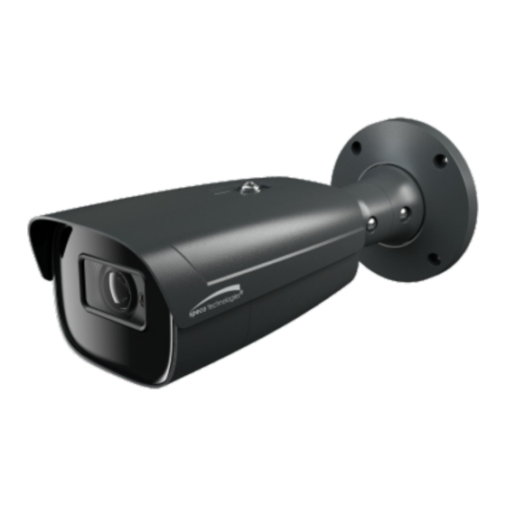
- Page 1 Quick Start Guide O4FB2M...
- Page 2 This owner's manual is designed to be a reference tool for your system. Please read this manual carefully before operating the unit and retain it for future reference. Should you require any technical assistance, contact Speco Technologies Tech Support at 1-800-645-5516 Important Safeguards and Warning 1.
- Page 3 Technologies reserves the right to modify these without notice and without incurring any obligation. Speco Technologies is not liable for any loss caused by improper operation. Note: Before installation, check the package and make sure that all components are included.
- Page 4 4 Screws CVBS&DC 4 Screws 8 Plastic screw (6.5×38mm) (PM 4×10mm) anchors IN cables 4 Screws (PA 4×25mm) Junction box 4 Rubber o-rings for screws 1Screw (PWM3×5mm) Overview Overview Ethernet Connector * Audio Input (MIC) Audio Output (HP) CVBS Video Output Alarm Input/Output Power Connector * Reset*...
-
Page 5: Connecting Network Cable
External microphone 1--ALM-COM 2--ALM-OPEN 3--ALM-INA 4--ALM-GND 12VDC/24VAC * It is recommended to install the water-proof connector for outdoor installations. Connecting Network Cable ① Loosen the nut from the main element. ② Run the network cable (without RJ 45 connector) through both elements. -
Page 6: Installation
Installation * Before you start, please make sure that the wall or ceiling is strong enough to withstand three times the weight of the camera. ① Open the mounting base and the upper cover of the junction box. Mounting base Upper cover ②... - Page 7 4× 6.6mm PM 4×10mm ⑤ Route the cables through the cable hole and connect the camera. Then install the camera onto the mounting base of the junction box. ⑥ Three-axis Adjustment-Before adjustment, preview the image of the camera on a monitor and then loosen the fixed screws to adjust the camera according to the figure below to get an optimum angle.
- Page 8 ② Install IP Scanner from the CD and run it after installation.Or download from https://www.specotech.com/ip-scanner/ 5C:F2:07:24:68:B9 O4FB2M ③ In the device list, you can view the IP address, model number, and MAC address of each device. Select the applicable device and double click to open up the web viewer.
- Page 9 The login interface is shown above. Default user name is admin and password is 1234. After logging in, follow directions to install applicable plugins if prompted.
Need help?
Do you have a question about the O4FB2M and is the answer not in the manual?
Questions and answers