Nortel Contivity 1700 Installing Manual
Hide thumbs
Also See for Contivity 1700:
- Install manual (218 pages) ,
- Product support bulletin (3 pages) ,
- Installing (158 pages)
Table of Contents
Advertisement
Quick Links
Download this manual
See also:
Installation Manual
Advertisement
Table of Contents

Related Manuals for Nortel Contivity 1700


Summary of Contents for Nortel Contivity 1700
- Page 1 Part No. 314711-D Rev 00 June 2004 600 Technology Park Drive Billerica, MA 01821-4130 Installing the Contivity 1700 *314711-D_Rev_00*...
- Page 2 In the interest of improving internal design, operational function, and/or reliability, Nortel Networks Inc. reserves the right to make changes to the products described in this document without notice. Nortel Networks Inc. does not assume any liability that may occur due to the use or application of the product(s) or circuit layout(s) described herein.
- Page 3 Canada requirements only Canadian Department of Communications Radio Interference Regulations This digital apparatus (Contivity 1700) does not exceed the Class A limits for radio-noise emissions from digital apparatus as set out in the Radio Interference Regulations of the Canadian Department of Communications.
- Page 4 30 days of purchase to obtain a credit for the full purchase price. “Software” is owned or licensed by Nortel Networks, its parent or one of its subsidiaries or affiliates, and is copyrighted and licensed, not sold. Software consists of machine-readable instructions, its components, data, audio-visual content (such as images, text, recordings or pictures) and related licensed materials including all whole or partial copies.
- Page 5 12.212 (for non-DoD entities) and 48 C.F.R. 227.7202 (for DoD entities). Customer may terminate the license at any time. Nortel Networks may terminate the license if Customer fails to comply with the terms and conditions of this license. In either event, upon termination, Customer must either return the Software to Nortel Networks or certify its destruction.
- Page 6 314711-D Rev 00...
-
Page 7: Table Of Contents
Chapter 1 Installing the Contivity 1700 chassis ......19 Description of the Contivity 1700 ......... 19 Preparing to install the Contivity 1700 . - Page 8 8 Contents Understanding the LEDs ..........34 Front panel LEDs .
- Page 9 Index ............89 Installing the Contivity 1700...
- Page 10 10 Contents 314711-D Rev 00...
-
Page 11: Installing The Contivity 1700
Figure 1 Front view of the Contivity 1700 ....... . 20 Figure 2 Placement of rubber feet on the bottom of the chassis . - Page 12 12 Figures Figure 30 ISDN BRI S/T interface card ........75 Figure 31 ISDN BRI U interface card .
-
Page 13: Installing The Contivity 1700
Tables Table 1 Items shipped with the Contivity 1700 ......21 Table 2 Interfaces and cables for the Contivity 1700 ..... . . 30 Table 3 Power cord requirements . - Page 14 14 Tables 314711-D Rev 00...
-
Page 15: Preface
17.) Before you begin This guide is intended for qualified service personnel who are installing the Contivity 1700 for the first time or who need to install or replace any of the following field replaceable units (FRUs): • LAN, WAN, and serial interface cards •... -
Page 16: Text Conventions
Preface Text conventions This guide uses the following text conventions: Indicates command names and options and text that bold Courier text you need to enter. Example: Use the command. show health Example: Enter terminal paging {off | on} italic text Indicates new terms and book titles. -
Page 17: Related Publications
Related publications For complete information about configuring, monitoring, and managing the Contivity 1700, refer to the following publications (included on the software CD): • Release notes provide the latest information, including brief descriptions of the new features, problems fixed in this release, and known problems and workarounds. -
Page 18: How To Get Help
URL to download a free copy of the Adobe Acrobat Reader. How to get help If you purchased a service contract for your Nortel Networks product from a distributor or authorized reseller, contact the technical support staff for that distributor or reseller for assistance. -
Page 19: Installing The Contivity 1700 Chassis
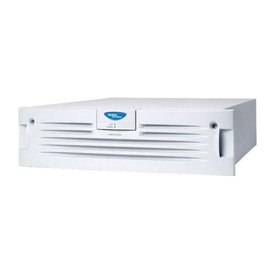
Preparing to install the Contivity 1700 Installing the chassis Description of the Contivity 1700 The Contivity 1700 enables scalable, secure, and robust IP VPNs across the public data network. The Contivity 1700 uses the infrastructure of the Internet to replace traditional remote access gear. -
Page 20: Preparing To Install The Contivity 1700
The Contivity 1700 chassis provides the following: • One 10/100 Ethernet* LAN port on the base system • One serial port for out-of-band management of the Contivity 1700 • Two expansion PCI slots that can contain interface cards and one Hardware Accelerator card •... -
Page 21: Shipment Contents
Contains Contivity VPN Client software and documentation on CD Inspect all items for shipping damage. If you detect any damage, do not install the Contivity 1700. Call the Nortel Networks Technical Solutions Center in your area (see “How to get help” on page 18). -
Page 22: Additional Equipment
22 Chapter 1 Installing the Contivity 1700 chassis Additional equipment You may need items that are not included in the Contivity 1700 shipping container. Before you begin the installation, make sure that you have all the cables, tools, and other equipment that you need. -
Page 23: Installing The Chassis
24). Installing the chassis on a flat surface If you decide to place the Contivity 1700 on a flat surface, make sure that the surface is large enough for the gateway and sturdy enough to support the combined weight of the Contivity 1700 and the cables that you attach to it. -
Page 24: Installing The Chassis In An Equipment Rack
Attaching the shelf in the equipment rack The Contivity 1700 ships with a rack-mount shelf to support the chassis in the equipment rack. To attach the shelf to the inside of the equipment rack: If the holes in the rack’s vertical supports are not threaded, attach a cage nut in... -
Page 25: Figure 3 Attaching The Cage Nuts To The Rack
Chapter 1 Installing the Contivity 1700 chassis 25 Figure 3 Attaching the cage nuts to the rack Rail without threaded holes Cage nut CS260003A Position the rack-mount shelf inside the rack as shown in Figure Align the holes in the shelf with holes in the front of the rack. -
Page 26: Mounting The Chassis In The Equipment Rack
Grip the two handles and firmly pull the bezel toward you to unsnap it from the chassis. Caution: Do not use the piece with the Nortel Networks logo and the LEDs as a handle. The first few times that you remove the front bezel, it may be somewhat difficult to remove because the ball studs and socket clips are new. -
Page 27: Figure 6 Replacing The Front Bezel
Chapter 1 Installing the Contivity 1700 chassis 27 Insert one of the supplied panhead screws through the bottom hole on each side of the shelf into the hole in the rack and tighten the screws (see Figure 4 on page 25). - Page 28 28 Chapter 1 Installing the Contivity 1700 chassis 314711-D Rev 00...
-
Page 29: Cabling The Gateway And Turning The Power On
Contivity 1700. Caution: Connect the cables to the built-in Ethernet port and to the interfaces on the option cards installed in the Contivity 1700 before you plug the power cord into the outlet. This chapter contains the following topics:... -
Page 30: Connecting Communications Cables
Table 2 lists the system ports and the ports provided on the optional interface cards that you can install in the Contivity 1700. The table also indicates whether you can obtain cables for the ports from Nortel Networks. Table 2 Interfaces and cables for the Contivity 1700... -
Page 31: Figure 7 Rear View Of The Contivity 1700
Chapter 2 Cabling the gateway and turning the power on 31 Figure 7 shows the back of the Contivity 1700. All interface cables and the power cord attach to the rear of the gateway. Figure 7 Rear view of the Contivity 1700... -
Page 32: Connecting The Power Cord
Caution: You should protect the Contivity 1700 by plugging it into a surge suppressor. Press and release the power switch on the rear of the Contivity 1700 (see Figure 7 on page 31) and wait for the gateway to boot. -
Page 33: Verifying A Successful Installation
(see “Connecting the power cord” on page 32). If the Contivity 1700 still does not boot, contact your local Nortel Networks Technical Solutions Center (see “How to get help” on page 18). -
Page 34: Understanding The Leds
34 Chapter 2 Cabling the gateway and turning the power on Understanding the LEDs This section describes the LEDs on the front panel of the Contivity 1700 and on the interface cards that have LEDs. You can confirm that the LAN and WAN interfaces are cabled properly by examining the LEDs. -
Page 35: Leds On The System 10/100Base Ethernet Port
The cable connections between the LAN port and the hub are good. The cable connections between the LAN port and the hub are faulty. Flashing The LAN port is sending or receiving network data. The frequency of the flashes increases with increased traffic. Installing the Contivity 1700... -
Page 36: 10/100Base Ethernet Interface Card Leds
36 Chapter 2 Cabling the gateway and turning the power on 10/100BASE Ethernet interface card LEDs Figure 10 shows the LEDs on the 10/100BASE Ethernet interface card. Figure 10 LEDs on the 10/100BASE Ethernet interface card Activity/Link 10/100 Mb/s CS260009A Table 6 describes the LEDs on the 10/100BASE Ethernet interface card. -
Page 37: 56/64K Csu/Dsu Wan Interface Card Leds
Red alarm LED is lit when a loss-of-signal (LOS) or out-of-frame (OOF) condition is detected on the receive signal. Yellow Yellow alarm LED is lit when the far-end equipment is in the red alarm condition. Green Normal operation. Installing the Contivity 1700... -
Page 38: Adsl Wan Interface Card Leds
38 Chapter 2 Cabling the gateway and turning the power on ADSL WAN interface card LEDs Figure 12 shows the LEDs on the ADSL WAN interface card. Figure 12 LEDs on the ADSL WAN interface card Tx/Rx LED Tx/Rx ADSL CONN CONN LED 10972EA... -
Page 39: T1/E1 Csu/Dsu Wan Interface Card Leds
Blue alarm LED is lit when receiving an upstream failure denoted by an alarm indication signal (AIS). LED 3 Yellow Yellow alarm LED is lit when the far-end equipment is in the red alarm condition. LED 4 Green Normal operation. Installing the Contivity 1700... -
Page 40: Quad T1/E1 Csu/Dsu Wan Interface Card Leds
40 Chapter 2 Cabling the gateway and turning the power on Quad T1/E1 CSU/DSU WAN interface card LEDs Figure 14 shows the LEDs on the quad T1/E1 CSU/DSU WAN interface card. Figure 14 LEDs on the quad T1/E1 CSU/DSU WAN interface card LED 1 LED 2 LED 3... -
Page 41: Single V.35/X.21 Wan Interface Card Leds
The signals CDC and DSR are on between the DSU and the adapter. LED 2 detects receive link status. LED 3 Green Power to the adapter is on and the onboard microcode is loaded. LED 4 Green Cable is detected. Installing the Contivity 1700... - Page 42 42 Chapter 2 Cabling the gateway and turning the power on 314711-D Rev 00...
-
Page 43: Configuring The Management Ip Interface
Configuring the management IP interface This chapter describes how to configure a management IP address, subnet mask, and default gateway address on a newly installed Contivity 1700. After you complete the procedures in this chapter, you will be able to configure and manage the Contivity 1700 using a Web browser from a PC. -
Page 44: Required Information
IP address for the management interface The management IP address must be accessible from one of the private physical interfaces on the Contivity 1700. For example, if you plan to assign IP address 10.2.3.3 with subnet mask 255.255.0.0 to the private physical interface, the management IP address must reside in the 10.2 network. -
Page 45: Configuring The Management Ip Address
Chapter 3 Configuring the management IP interface 45 Configuring the management IP address You use the serial interface to assign the Contivity 1700 a management IP address and subnet mask so that you can then use a Web browser for management. - Page 46 46 Chapter 3 Configuring the management IP interface The serial main menu appears. Main Menu: System is currently in NORMAL mode. 1) Interfaces 2) Administrator 3) Default Private Route Menu 4) Default Public Route Menu 5) Create A User Control Tunnel (IPsec) Profile 6) Restricted Management Mode FALSE 7) Allow HTTP Management...
-
Page 47: Installing The Contivity 1700
The subnet mask prompt appears. Old Subnet Mask = 0.0.0.0 New Subnet Mask = At the New Subnet Mask prompt, type the subnet mask for the management IP address and press Enter. The Speed/Duplex prompt appears. Installing the Contivity 1700... - Page 48 13 Go to the next section, “Testing the configuration,” to verify that you can access the Contivity 1700 from a Web browser. For detailed information about configuring and managing the Contivity 1700, refer to the documentation on the Contivity software CD. 314711-D Rev 00...
-
Page 49: Testing The Configuration
After you assign a management IP address to the Contivity 1700, start your Web browser to verify that you can access the gateway from the browser. To manage the Contivity 1700 using the GUI, your PC must be running one of the following browsers: •... -
Page 50: Figure 16 Welcome Screen
50 Chapter 3 Configuring the management IP interface Figure 16 Welcome screen 314711-D Rev 00... -
Page 51: Troubleshooting
Check the physical connections on the Contivity 1700, especially the LAN cable and the power cord. If you still cannot connect to the Contivity 1700 using a browser, connect a terminal or PC to the gateway with the serial cable and check the management IP address listed in the serial menu (see “Configuring the management IP address”... - Page 52 52 Chapter 3 Configuring the management IP interface 314711-D Rev 00...
-
Page 53: Installing Option Cards And Dimms
Chapter 4 Installing option cards and DIMMs This chapter provides instructions on how to install and replace the following field replaceable units (FRUs) in the Contivity 1700: • LAN, WAN, and serial interface cards • Hardware Accelerator card • Dual inline memory modules (DIMMs) -
Page 54: Shutting Down The System To Add Or Replace Hardware
Wait for the system to shut down. Disconnect the power cord from the power outlet and then disconnect the cord from the Contivity 1700. The power receptacle is located on the rear of the Contivity 1700 (see Figure 7 on page 31). -
Page 55: Removing The Front Bezel And Top Cover
To install option cards or DIMMs, you must remove the front bezel and the top cover from the gateway. To remove the front bezel: Shut down the Contivity 1700 using the Web GUI or the command line interface and then unplug it as described in “Shutting down the system to add or replace hardware”... -
Page 56: Figure 18 Removing The Top Cover
To remove the top cover: If the Contivity 1700 is installed in an equipment rack, remove it from the rack. At the front of the chassis, remove the 2 panhead screws that secure the bottom of the chassis to the equipment rack. -
Page 57: Figure 19 Location Of Option Card Slots And Dimms On The System Board
Chapter 4 Installing option cards and DIMMs 57 Lift the lid 2 or 3 inches and pull it off the chassis. The Contivity 1700 system board is now exposed. Figure 19 shows the location of the option card slots and the DIMMs on the system board. -
Page 58: Attaching The Antistatic Wrist Strap
58 Chapter 4 Installing option cards and DIMMs Attaching the antistatic wrist strap Nortel Networks ships the Contivity 1700 with an antistatic wrist strap. The antistatic wrist strap directs the discharge of static electricity from your body to the chassis of the gateway to avoid damage to sensitive electronic components. -
Page 59: Installing And Replacing Option Cards
The Contivity 1700 has two slots for option cards (see Figure 19 on page 57). This section provides instructions on adding new option cards to the Contivity 1700 or, if necessary, replacing an existing card. Table 12 lists the option cards that you can install in the Contivity 1700. - Page 60 60 Chapter 4 Installing option cards and DIMMs To install or replace an interface card or a Hardware Accelerator card: Shut down the Contivity 1700 using the Web GUI or the command line interface and then unplug it as described in “Shutting down the system to add...
-
Page 61: Figure 21 Removing An Option Card Or A Filler Panel
Remove the filler panel screw and pull out the filler panel (or the option card that you are replacing) from the slot (Figure 21). Figure 21 Removing an option card or a filler panel Screwdriver Phillips slots screw Option card Option card slot 1 Option card slot 2 Motherboard CS160020A Installing the Contivity 1700... -
Page 62: Figure 22 Installing An Option Card
62 Chapter 4 Installing option cards and DIMMs Slide the option card into the intended slot (Figure 22). Make sure that the card is seated firmly in the slot. If the card is not seated properly, it will not work. Figure 22 Installing an option card Option card Option card... -
Page 63: Figure 23 Replacing The Front Bezel
Chapter 4 Installing option cards and DIMMs 63 10 If the Contivity 1700 is installed in an equipment rack, mount it in the rack. Set the Contivity 1700 on the rack-mount shelf in the rack. b Insert one of the panhead screws through the bottom hole on each side of the shelf into the hole in the rack and tighten the screws. -
Page 64: Installing And Replacing Dimms
64 Chapter 4 Installing option cards and DIMMs Installing and replacing DIMMs The Contivity 1700 has two slots for dual inline memory modules (DIMMs) (see Figure 19 on page 57). Unless you ordered additional memory, the Contivity 1700 is shipped with one 128 MB DIMM installed. You can upgrade memory in the gateway by installing a second 128 MB DIMM. -
Page 65: Figure 24 Installing And Removing A Dimm
Pull up the locking lever on either side of the DIMM to snap it into position. Figure 24 Installing and removing a DIMM Alignment keys To remove DIMMs, pull back locking levers and pull out DIMM. To install DIMMs, pull back locking levers and push in DIMM. Locking lever CS160008A Installing the Contivity 1700... - Page 66 Using a screwdriver, insert and tighten the 4 screws to secure the cover to the chassis. 11 If the Contivity 1700 is installed in an equipment rack, mount it in the rack. Set the Contivity 1700 on the rack-mount shelf in the rack.
-
Page 67: Technical Specifications
Appendix A Technical specifications This appendix provides technical specifications for the Contivity 1700 chassis and its interfaces. Chassis specifications Table 13 lists physical, electrical, and environmental specifications for the chassis. Table 13 Physical, electrical, and environmental specifications Specification Description Physical Height 3.5 in. -
Page 68: System Ports
68 Appendix A Technical specifications System ports The Contivity 1700 system board provides the following built-in interfaces: • 10/100BASE Ethernet LAN port • Serial port This section provides information about the 10/100BASE Ethernet LAN port and the serial port on the system board. -
Page 69: Serial Port
Chapter 3, “Configuring the management IP interface,” on page 43). The serial cable provided with the Contivity 1700 is a DB9/DB25-to-DB9/DB25 cable. This cable provides a crossover connection (transmit-to-receive and receive-to-transmit). The DB9 connector goes into the gateway and the other DB9 or DB25 connector goes into your workstation. -
Page 70: Modem Cable Specifications
70 Appendix A Technical specifications Modem cable specifications If you need to connect a modem to a Contivity 1700, you must obtain an appropriate modem cable. The modem cable must have a 9-pin D-sub plug that connects to the Contivity 1700 serial port and a 25-pin D-sub plug that connects to... -
Page 71: Hardware Option Cards
Appendix A Technical specifications 71 Hardware option cards The Contivity 1700 provides two PCI slots that support a combination of the following option cards: • Hardware Accelerator card • 10/100BASE Ethernet interface card • 56/64K CSU/DSU WAN interface card •... -
Page 72: 10/100Base Ethernet Interface Card
The connector on the 56/64K CSU/DSU WAN interface card accommodates an 8-pin RJ-48 modular patch cord. These cables are commonly sold as Category 5, or Ethernet, cables. Note: Nortel Networks does not supply an interface cable with the 56/64K CSU/DSU WAN interface card. 314711-D Rev 00... -
Page 73: Table 17 56/64K Csu/Dsu Cable Pinouts For Crossover Connection
Transmit tip Receive ring Transmit ring The cable will operate properly if pins 3, 4, 5, and 6 are not connected. Caution: For crossover connections, do not use Ethernet cable. The link will not be established. Installing the Contivity 1700... -
Page 74: Adsl Wan Interface Card
74 Appendix A Technical specifications Table 18 provides the 56/64K CSU/DSU cable pinouts for a straight-through connection. Table 18 56/64K CSU/DSU cable pinouts for straight-through connection Nortel Networks termination Remote termination Signal Pin # to Pin # Signal Transmit tip... -
Page 75: Isdn Bri Interface Card
Figure 30 shows the ISDN BRI S/T interface card. Figure 30 ISDN BRI S/T interface card ISDN-ST 10972EA Figure 31 shows the ISDN BRI U interface card. Figure 31 ISDN BRI U interface card ISDN-U 10972EB Installing the Contivity 1700... -
Page 76: Table 20 Isdn Bri S/T Cable Pinouts
The connector on the ISDN BRI S/T and ISDN BRI U interface cards accommodates an 8-pin RJ-45 modular patch cord. These cables are commonly sold as Category 5, or Ethernet, cables. Note: Nortel Networks does not supply a cable with the ISDN BRI interface cards. Table 20 provides the ISDN BRI S/T cable pinouts. -
Page 77: T1/E1 Csu/Dsu Wan Interface Card
RJ-48 modular patch cord. These cables are commonly sold as Category 5, or Ethernet, cables. Note: Nortel Networks does not supply the T1/E1 CSU/DSU WAN interface cable with the WAN interface card. The cable you use should be wired in accordance with EIA-568-A wiring style. -
Page 78: Table 22 T1/E1 Csu/Dsu Cable Pinouts For Crossover Connection
T1/E1 CSU/DSU will not work to specifications. Data may be corrupted. Table 23 provides the T1/E1 CSU/DSU cable pinouts for a straight-through connection. Table 23 T1/E1 CSU/DSU cable pinouts for straight-through connection Nortel Networks termination Remote termination Signal Pin # to Pin # Signal... -
Page 79: Quad T1/E1 Csu/Dsu Wan Interface Card
8-pin RJ-48 modular patch cord. These cables are commonly sold as Category 5, or Ethernet, cables. Note: Nortel Networks does not supply cables with the quad T1/E1 CSU/DSU interface card. The cables you use should be wired in accordance with EIA-568-A wiring style. -
Page 80: V.90 Modem Interface Card
80 Appendix A Technical specifications V.90 modem interface card The V.90 modem interface card has two RJ-11 connectors that provide the signals needed to interface to an incoming telephone line and to telephone equipment. Figure 34 shows the V.90 modem interface card. Figure 34 V.90 modem interface card 10973EA Included in the accessory box is a 7-foot RJ-11 cable to attach to a telephone jack. -
Page 81: Table 25 V.35 Cable Pinouts
7B no conn Note 1 DSRA pair 8A DSRB pair 8B DTRA pair 9A DTRB pair 9B no conn Note 1 DCDA pair 10A DCDB pair 10B no conn Note 1 pair 11A pair 11B Installing the Contivity 1700... -
Page 82: Table 26 X.21 Cable Pinouts
82 Appendix A Technical specifications Table 25 V.35 cable pinouts (continued) Standard-wired Pair number Special-wired end 28-pin male Signal name and conductor end 34-pin male Notes pair 12A M0<-SIGNAL GROUND pair 12B Note 2 M1<-SIGNAL GROUND pair 13A Note 2 pair 13B no conn Note 1... -
Page 83: Installing The Contivity 1700
3. Wires 13B and 14B connect to pin 8 in the 15-pin connector. 4. At each end, the cable shield and connector shell must connect to pin 1 of the connector. 5. Do not interconnect Shield to Signal Ground because these are separate signals. Installing the Contivity 1700... -
Page 84: Dual V.35 Wan Interface Card
84 Appendix A Technical specifications Dual V.35 WAN interface card The dual V.35 WAN interface card has two DB26 connectors that provide the signals needed to interface to V.35 equipment. Figure 36 shows the dual V.35 WAN interface card. Figure 36 Dual V.35 WAN interface card CS260016A Note: The dual V.35 WAN interface card is no longer available for purchase. -
Page 85: Table 27 Db26-To-V.35 Cable Pinouts
7B no conn pair 8A pair 8B no conn pair 9A pair 9B no conn pair 10A pair 10B no conn SGND pair 11A pair 11B no conn CGND pair 12A pair 12B no conn Installing the Contivity 1700... -
Page 86: Hssi Wan Interface Card
86 Appendix A Technical specifications HSSI WAN interface card The HSSI WAN interface card has a 50-pin SCSI II female connector that provides the signals needed to interface to a T3 modem or modem eliminator. Figure 37 shows the HSSI WAN interface card. Figure 37 HSSI WAN interface card CS460003A Included in the accessory box is a cable that maps the T3 signals out to a 50-pin... -
Page 87: Installing The Contivity 1700
Appendix A Technical specifications 87 Table 28 T3 cable pinouts (continued) 50-pin SCSI male Signal name 50-pin SCSI male TESTA Installing the Contivity 1700... - Page 88 88 Appendix A Technical specifications 314711-D Rev 00...
-
Page 89: Index
49 connector 68 LEDs 35 56/64K CSU/DSU WAN interface card cable pinouts 73 cables connector 72 available from Nortel Networks 30 described 72 connecting to the gateway 31 installing 59 ordering 30 LEDs 37 power. See AC power cord... - Page 90 V.35/X.21 WAN interface 80 T1/E1 CSU/DSU WAN interface 77 field replaceable units (FRUs), installing 53 V.90 modem interface 80 front bezel Contivity 1700 removing 26, 55 configuring management IP address for 43 replacing 27, 63 connecting cables to 29...
- Page 91 75 installing 59 option cards installing 59 LAN interface card specifications 71 connector 68 See also 10/100BASE Ethernet interface card, installing 59 Hardware Accelerator card, serial interface LEDs 36 cards, WAN interface cards specifications 72 Installing the Contivity 1700...
- Page 92 79 serial port 69 described 79 system ports 68 installing 59 subnet mask, defined 44 LEDs 40 support, Nortel Networks 18 system LAN port cable specifications 68 rack, equipment, specifications 22 connector 68 rack-mount considerations 24 LEDs 35 rack-mount shelf 24...
- Page 93 V.35 WAN interface card. See dual V.35 WAN interface card V.35/X.21 WAN interface card. See single V.35/X.21 WAN interface card V.90 modem interface card cable pinouts 80 connectors 80 installing 59 verifying a successful installation 33 verifying the management IP interface 49 Installing the Contivity 1700...
- Page 94 94 Index 314711-D Rev 00...
Need help?
Do you have a question about the Contivity 1700 and is the answer not in the manual?
Questions and answers