
Subscribe to Our Youtube Channel
Related Manuals for THORLABS PSDM2


Summary of Contents for THORLABS PSDM2
- Page 1 PSDM2, PSDM4, and PSDM5 High-Resolution, Non-Contact, Position-Sensing Detector and Mount Operating Manual...
-
Page 2: Table Of Contents
4.1. Spectral Response............................8 Lateral Detectors (PSDM2 and PSDM4)..........................8 Quadrant Detector (PSDM 5) ............................8 4.2. Standard Silicon Lateral Detectors (PSDM2 and PSDM4)................ 9 4.3. InGaAs Quadrant Detector (PSDM5) ......................11 Part 5. PSDM Sensing Principle ........................ 12 5.1. PSDM Lateral Detector ..........................12 Normalize Position Independent of Power Variations....................13... - Page 3 Resolution vs. Beam Spot Power at Several Wavelengths ..........17 Figure 12: Beam Spot Power Noise Influence on Difference ............... 18 Figure 13: Electrical Model of a One-Dimensional Lateral Detector ........... 19 Figure 14: Recommended Connection to Data Acquisition Card ............20 12400-D02, 10/26/2007 Page 3 www.thorlabs.com...
-
Page 4: Part 1. Features And Applications
• SUM signal for source power indication, source power control feedback, or setup alignment • Stable mechanics enable long-term low drift measurements • Mounting holes for Thorlabs’ cage system and SM1 threaded components facilitates lens mounting • 16-pin header enables sampling of low level signals for fast external signal processing •... -
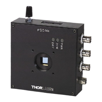
Page 5: Figure 1: Psdm Connections, Mounting Holes, And Switches
PSDM Series Position Sensing Systems Figure 1: PSDM Connections, Mounting Holes, and Switches 12400-D02, 10/26/2007 Page 5 www.thorlabs.com... -
Page 6: Part 2. Introduction
PSDM2 and PSDM4 have 1D and 2D lateral detectors, respectively, while PSDM5 has a quadrant detector. Upon request, PSDM2 and PSDM4 can be equipped with a UV enhanced lateral detector, enabling response down to 200 nm. -
Page 7: Part 3. Output Signals
Signals can be connected through either BNC connectors (X, Y, and SUM only) or through a 16-pin male header. Figure 3: 16-Pin Header Viewed from the Top Signal … Reference/GND 2, 4, 6 X:A current X:B current Y:A current Y:B current 12400-D02, 10/26/2007 Page 7 www.thorlabs.com... -
Page 8: Part 4. Technical Data
PSDM Series Position Sensing Systems Part 4. Technical Data 4.1. Spectral Response Lateral Detectors (PSDM2 and PSDM4) Figure 4: Lateral Detector Spectral Response Quadrant Detector (PSDM 5) Figure 5: Quadrant Detector Spectral Response 12400-D02, 10/26/2007 Page 8 www.thorlabs.com... -
Page 9: Standard Silicon Lateral Detectors (Psdm2 And Psdm4)
PSDM Series Position Sensing Systems 4.2. Standard Silicon Lateral Detectors (PSDM2 and PSDM4) Parameter Units Typical Conditions Housing Dimensions Length Height Width Bottom to Detector Center Power Consumption <3 Wavelength Range 1100 Detector Dimensions PSDM 2 PSDM 4 10 x 10 Resolves change in position: Δ... - Page 10 >10 kΩ, Low Capacitance Load DIFF X and Y >10 kΩ, Low Capacitance Load >10 kΩ, Low Capacitance Load Signal Output Bandwidth X and Y Current -3 dB DIFF X, DIFF Y, SUM -3 dB 12400-D02, 10/26/2007 Page 10 www.thorlabs.com...
-
Page 11: Ingaas Quadrant Detector (Psdm5)
DIFF X and Y Signal Output Bandwidth X and Y Current -3 dB Diff X, Y, and SUM -3 dB † See section 6.1 (page 16) for more information ‡ See section 5.2 (page 14) for more information 12400-D02, 10/26/2007 Page 11 www.thorlabs.com... -
Page 12: Part 5. Psdm Sensing Principle
The first amplifier stage converts detector currents to corresponding voltages through transimpedance amplifiers (TIA): ⋅ Current The X and SUM output signals are difference and sum signals, respectively, determined from the voltage signals X:A CURRENT and X:B CURRENT. 12400-D02, 10/26/2007 Page 12 www.thorlabs.com... -
Page 13: Normalize Position Independent Of Power Variations
(PC AD-converter card), by software. − 2 ⋅ NORM Figure 8: Lateral Detector Position Responce The lateral detector models does not reference low level signals to ground (see section 6.2). 12400-D02, 10/26/2007 Page 13 www.thorlabs.com... -
Page 14: Psdm Quadrant Detector
(see transimpedance). Figure 9: Quadrant Detector Photodiode Elements Normalized position independent of power level can be computed externally via DIFF NORM If using low level signals (X:A CURRENT, etc.), the normalized position can be computed from 12400-D02, 10/26/2007 Page 14 www.thorlabs.com... -
Page 15: Position Response
Figure 10: Normalized Quadrant X Position Signal as a Function of Actual Position A rectangular spot with sides LX and LY that has uniform intensity gives a linear position response (no spot truncation and distance between quadrants disregarded). BEAMSPOT NORM 12400-D02, 10/26/2007 Page 15 www.thorlabs.com... -
Page 16: Part 6. Application Information
PSDM gain to overcome measuring equipment noise (digital oscilloscopes can seldom resolve signals below 1 mV). Noise can be attributed to detector shot noise, thermal noise (PSDM2 and PSDM4 only), electronics transimpedance amplifier noise, and beam spot noise (i.e. position and power noise). -
Page 17: Figure 11: Resolution Vs. Beam Spot Power At Several Wavelengths
Figure 11: Resolution vs. Beam Spot Power at Several Wavelengths The PSDM2 and PSDM4 beam power normalized position signal is shown versus beam spot power. Each curve represents a different wavelength (refer to the PSDM web page and the S/N ratio above). -
Page 18: Beam Spot Power Noise
X:A + X:B as beam power control feedback. Figure 12: Beam Spot Power Noise Influence on Difference Beam spot power noise influence on resolution (PSDM2 and PSDM4). The current noise at detector terminals/electrodes X:A and X:B originating from beam power noise have equal magnitude at mid position (correlated). -
Page 19: Lateral Detector Saturation
Preferably, use electrical modulation of source power (laser or LED current modulation). In applications where beam path length in air is limited or where high resolution is not required, an optical chopper can be used such as the Thorlabs MC1000. In this case, use the photocurrent signals X:A and X:B and a modulation frequency of 500 to 1000 Hz. -
Page 20: Sampling Techniques
Connect PSDM GND to the card GND through the PSDM GND 4 mm socket as shown in the figure below. Figure 14: Recommended Connection to Data Acquisition Card 12400-D02, 10/26/2007 Page 20 www.thorlabs.com... -
Page 21: Part 7. Warranty
PSDM Series Position Sensing Systems Part 7. Warranty General Product Warranty Thorlabs warrants that all products sold will be free from defects in material and workmanship, and will conform to the published specifications under normal use and service when correctly installed and maintained. -
Page 22: Part 8. Regulatory
8.1. Waste Treatment is Your Responsibility If you do not return an “end of life” unit to Thorlabs, you must hand it to a company specialized in waste recovery. Do not dispose of the unit in a litter bin or at a public waste disposal site. -
Page 23: Part 9. Thorlabs, Inc. Worldwide Contacts
PSDM Series Position Sensing Systems Part 9. Thorlabs, Inc. Worldwide Contacts For technical support or sales inquiries, please visit us at www.thorlabs.com/contact for our most up- to-date contact in information. USA, Canada, and South America UK and Ireland Thorlabs, Inc. - Page 24 Thorlabs, Inc. 435 Route 206N Newton, NJ 07860 USA Phone: (973) 579-7227 ♦ Fax: (973) 300-3600 www.thorlabs.com...
Need help?
Do you have a question about the PSDM2 and is the answer not in the manual?
Questions and answers