Table of Contents
Advertisement
Quick Links
CDO
OM-03200-OB01
May 31, 1988
Rev. E 04/23/02
INSTALLATION, OPERATION,
AND MAINTENANCE MANUAL
WITH PARTS LIST
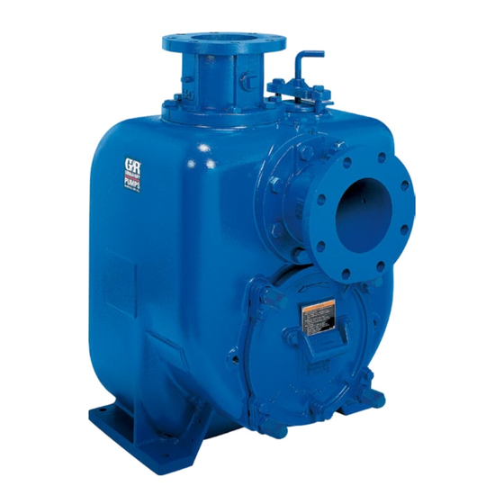
U SERIES PUMP
MODEL
U3B65-B
INCLUDING: /F
THE GORMAN-RUPP COMPANY D MANSFIELD, OHIO
GORMAN-RUPP OF CANADA LIMITED
ST. THOMAS, ONTARIO, CANADA
D
Printed in U.S.A.
E
Copyright by the Gorman-Rupp Company
Advertisement
Table of Contents

Related Manuals for GORMAN-RUPP PUMPS U3B65-B


Summary of Contents for GORMAN-RUPP PUMPS U3B65-B
- Page 1 Rev. E 04/23/02 INSTALLATION, OPERATION, AND MAINTENANCE MANUAL WITH PARTS LIST U SERIES PUMP MODEL U3B65-B INCLUDING: /F THE GORMAN-RUPP COMPANY D MANSFIELD, OHIO GORMAN-RUPP OF CANADA LIMITED ST. THOMAS, ONTARIO, CANADA Printed in U.S.A. Copyright by the Gorman-Rupp Company...
- Page 2 TABLE OF CONTENTS INTRODUCTION ..........PAGE I --- 1 SAFETY --- SECTION A .
-
Page 3: Table Of Contents
TABLE OF CONTENTS (continued) TROUBLESHOOTING --- SECTION D ......PAGE D --- 1 PREVENTIVE MAINTENANCE . - Page 4 U SERIES OM -- 03200 INTRODUCTION This Installation, Operation, and Maintenance priming centrifugal model. The pump is designed manual is designed to help you achieve the best for high-efficiency, self-priming service, and is ca- performance and longest life from your Gorman- pable of handling low pH resistance residues and Rupp pump.
- Page 5 U SERIES OM -- 03200 SAFETY --- SECTION A This information applies to U Series ba- sic pumps. Gorman-Rupp has no con- trol over or particular knowledge of the power source which will be used. Refer After the pump has been positioned, to the manual accompanying the power make certain that the pump and all pip- source before attempting to begin...
- Page 6 OM -- 03200 U SERIES Never run this pump backwards. Be cer- Use lifting and moving equipment in tain that rotation is correct before fully good repair and with adequate capacity engaging the pump. to prevent injuries to personnel or dam- age to equipment.
- Page 7 See Figure 1 for the approximate physical dimen- configuration, and priming must be tailored to the sions of this pump. OUTLINE DRAWING Figure 1. Pump Model U3B65-B INSTALLATION PAGE B -- 1...
- Page 8 OM -- 03200 U SERIES PREINSTALLATION INSPECTION POSITIONING PUMP The pump assembly was inspected and tested be- Lifting fore shipment from the factory. Before installation, Use lifting equipment with a capacity of at least inspect the pump for damage which may have oc- 2605 pounds (1181,6 kg).
- Page 9 U SERIES OM -- 03200 tion losses. See the performance curve and oper- Installation closer to the pump may result in erratic ating range shown on Page E-1 to be sure your readings. overall application allows pump to operate within the safe operation range.
- Page 10 OM -- 03200 U SERIES ommendations when selecting and applying the If two suction lines are installed in a single sump, pipe dope. The pipe dope should be compatible the flow paths may interact, reducing the efficiency with the liquid being pumped. of one or both pumps.
- Page 11 U SERIES OM -- 03200 DISCHARGE LINES NOTE The bypass line should be sized so that it does not affect pump discharge capacity; however, the by- pass line should be at least 1 inch in diameter to Siphoning minimize the chance of plugging. Do not terminate the discharge line at a level lower In low discharge head applications (less than 30 than that of the liquid being pumped unless a si-...
- Page 12 OM -- 03200 U SERIES If a manual shut-off valve is installed in a bypass line, it must not be left closed during operation. A closed manual shut- off valve may cause a pump which has lost prime to continue to operate with- Figure 3.
- Page 13 U SERIES OM -- 03200 reach its designed capacity or head. Valve closing Air Release Valve Installation pressure is dependent upon the discharge head of the pump at full capacity. The range of the valve The Automatic Air Release Valve must be inde- closing pressure is established by the tension rate pendently mounted in a horizontal position and of the spring as ordered from the factory.
- Page 14 OM -- 03200 U SERIES cific application. Most couplings require a specific gap or clearance between the driving and the driven shafts. Refer to the coupling manufacturer’s service literature. ALIGNMENT Align spider insert type couplings by using calipers to measure the dimensions on the circumference The alignment of the pump and its power source is of the outer ends of the coupling hub every 90 de- critical for trouble-free mechanical operation.
- Page 15 U SERIES OM -- 03200 V-Belt Drives When using V-belt drives, the power source and the pump must be parallel. Use a straightedge along the sides of the pulleys to ensure that the pul- Do not operate the pump without the leys are properly aligned (see Figure 6C).
- Page 16 OM -- 03200 U SERIES OPERATION --- SECTION C Review all SAFETY information in Section A. Add liquid to the pump casing when: 1. The pump is being put into service for the Follow the instructions on all tags, labels and de- first time.
- Page 17 OM -- 03200 U SERIES be damaged and performance adversely affected sure which could damage pipe ends, gaskets, by incorrect rotation. If pump performance is not sprinkler heads, and any other fixtures connected within the specified limits (see the curve on page to the line.
- Page 18 OM -- 03200 U SERIES move plates, covers, gauges, or fittings Block the suction line and start the pump. At oper- from an over-heated pump. Liquid with- ating speed the pump should pull a vacuum of 20 in the pump can reach boiling tempera- inches (508,0 mm) or more of mercury.
- Page 19 OM -- 03200 U SERIES large solids from clogging the drain port and pre- curately by placing a contact-type thermometer venting the pump from completely draining, insert against the housing. Record this temperature for a rod or stiff wire in the drain port, and agitate the future reference.
-
Page 20: Troubleshooting
U SERIES OM -- 03200 TROUBLESHOOTING --- SECTION D Review all SAFETY information in Section A. Before attempting to open or service the pump: 1. Familiarize yourself with this manual. 2. Lock out or disconnect the power source to ensure that the pump will remain inoperative. - Page 21 OM -- 03200 U SERIES TROUBLE POSSIBLE CAUSE PROBABLE REMEDY PUMP FAILS TO Plug in threaded passage through in- Tighten or install plug. PRIME (cont.) terior wall of casing loose or missing. Air leak in suction line. Correct leak. PUMP STOPS OR FAILS TO DELIVER Lining of suction hose collapsed.
-
Page 22: Preventive Maintenance
U SERIES OM -- 03200 TROUBLE POSSIBLE CAUSE PROBABLE REMEDY EXCESSIVE NOISE Cavitation in pump. Reduce suction lift and/or friction losses in suction line. Record vac- uum and pressure gauge readings and consult local representative or factory. Pumping entrained air. Locate and eliminate source of air bubble. - Page 23 OM -- 03200 U SERIES Preventive Maintenance Schedule Service Interval* Item Daily Weekly Monthly Semi- Annually Annually General Condition (Temperature, Unusual Noises or Vibrations, Cracks, Leaks, Loose Hardware, Etc.) Pump Performance (Gauges, Speed, Flow) Bearing Lubrication Seal Lubrication (And Packing Adjustment, If So Equipped) V-Belts (If So Equipped) Air Release Valve Plunger Rod (If So Equipped)
-
Page 24: Pump Maintenance And Repair
MAINTENANCE AND REPAIR OF THE WEARING PARTS OF THE PUMP WILL MAINTAIN PEAK OPER- ATING PERFORMANCE. STANDARD PERFORMANCE FOR PUMP MODEL U3B65-B AND U3B65-- B /F Based on 70_ F (21_ C) clear water at sea level Contact the Gorman-Rupp Company to verify per- formance or part numbers. - Page 25 OM -- 03200 U SERIES SECTION DRAWING Figure 1. Pump Model U3B65---B And U3B65---B /F PAGE E -- 2 MAINTENANCE & REPAIR...
-
Page 26: Parts Lists
OM -- 03200 U SERIES PARTS LIST Pump Model U3B65---B And U3B65---B /F (From S/N 979494 up) If your pump serial number is followed by an “N”, your pump is NOT a standard production model. Contact the Gorman-Rupp Company to verify part numbers. ITEM PART NAME PART... - Page 27 OM -- 03200 U SERIES SECTION DRAWING Figure 2. 44163---141 Repair Rotating Assembly PAGE E -- 4 MAINTENANCE & REPAIR...
- Page 28 OM -- 03200 U SERIES PARTS LIST 44163---141 Repair Rotating Assembly ITEM PART MAT’L PART NAME NUMBER CODE IMPELLER 38619---015 1718H SEAL ASSY 46512---074 --- --- --- SEAL PLATE GASKET 10959G 19410 INBOARD OIL SEAL S1352 --- --- --- BEARING HOUSING 38251---508 17180 INBOARD BALL BEARING...
-
Page 29: Pump And Seal Disassembly And Reassembly
OM -- 03200 U SERIES PUMP AND SEAL DISASSEMBLY 3. Allow the pump to completely cool if overheated. AND REASSEMBLY 4. Check the temperature before opening any covers, plates, or Review all SAFETY information in Section A. plugs. 5. Close the suction and discharge Follow the instructions on all tags, label and de- valves. -
Page 30: Rotating Assembly Removal
U SERIES OM -- 03200 Individual parts are not sold separately. shaft). When the impeller breaks loose, remove the wood block and lathe dog. Do not fully unscrew the impeller from the shaft at this time. Rotating Assembly Removal (Figure 1) (Figure 2) Remove the hardware (23 and 24) from the pump casing (1). -
Page 31: Impeller Removal
OM -- 03200 U SERIES Impeller Removal should be performed only in a properly-e- quipped shop by qualified personnel. (Figure 2) Remove the bearing housing drain plug (19) and Unscrew the impeller from the shaft in a counter- drain the lubricant. Clean and reinstall the drain clockwise direction (when facing the impeller). -
Page 32: Shaft And Bearing Reassembly And Installation
U SERIES OM -- 03200 foreign material. Failure to do so will great- NOTE ly shorten bearing life. Do not spin dry If a hot oil bath is used to heat the bearings, both the bearings. This may scratch the balls or oil and the container must be absolutely clean. -
Page 33: Seal Reassembly And Installation
OM -- 03200 U SERIES Press the outboard oil seal (12) into the bearing The seal is not normally reused because wear pat- cap (11) with the lip positioned as shown in Figure terns on the finished faces cannot be realigned 2. -
Page 34: Impeller Installation
U SERIES OM -- 03200 ROTATING RETAINER SPRING SPRING ELEMENT CENTERING SEAL WASHER PLATE O-RINGS IMPELLER IMPELLER SHAFT IMPELLER STATIONARY SHIMS SEAT BELLOWS STATIONARY DRIVE BAND ELEMENT Figure 5. 46512---074 Seal Assembly installed over the threads of the impeller shaft to ease installation of the rotating seal components. -
Page 35: Rotating Assembly Installation
OM -- 03200 U SERIES NOTE NOTE At the slightest sign of binding, immediately back An alternate method of adjusting this clearance is to the impeller off, and check the threads for dirt. Do reach through the priming port with a feeler gauge not try to force the impeller onto the shaft. -
Page 36: Pressure Relief Valve Maintenance
U SERIES OM -- 03200 pump casing. Be sure the wear plate does not bind ounces (0,59 liters) of SAE No. 30 non-detergent oil against the impeller. (so it is above the level of the internal casting). Clean and reinstall the vented plug. Maintain the oil NOTE at this level. - Page 37 For U.S. and International Warranty Information, Please Visit www.grpumps.com/warranty or call: U.S.: 419−755−1280 International: +1−419−755−1352 For Canadian Warranty Information, Please Visit www.grcanada.com/warranty or call: 519−631−2870 THE GORMAN-RUPP COMPANY D MANSFIELD, OHIO GORMAN-RUPP OF CANADA LIMITED ST. THOMAS, ONTARIO, CANADA...
Need help?
Do you have a question about the U3B65-B and is the answer not in the manual?
Questions and answers