GORMAN-RUPP PUMPS Ultra VS3A60-B Installation, Operation And Maintenance Manual
Hide thumbs
Also See for Ultra VS3A60-B:
Table of Contents

Related Manuals for GORMAN-RUPP PUMPS Ultra VS3A60-B


Summary of Contents for GORMAN-RUPP PUMPS Ultra VS3A60-B
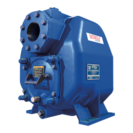
- Page 1 OM-06012-03 July 7, 2020 REV A - 9/17/20 INSTALLATION, OPERATION, AND MAINTENANCE MANUAL WITH PARTS LIST ULTRA V PUMP MODEL VS3A60-B INCLUDING: /WW GORMAN‐RUPP PUMPS www.grpumps.com 2020 Gorman‐Rupp Pumps Printed in U.S.A.
- Page 2 Register your new Gorman‐Rupp pump online at www.grpumps.com Valid serial number and e‐mail address required. RECORD YOUR PUMP MODEL AND SERIAL NUMBER Please record your pump model and serial number in the spaces provided below. Your Gorman‐Rupp distributor needs this information when you require parts or service. Pump Model: Serial Number:...
-
Page 3: Table Of Contents
TABLE OF CONTENTS INTRODUCTION ..........PAGE I - 1 SAFETY - SECTION A . - Page 4 TABLE OF CONTENTS (continued) Clog Removal and Wear Plate Clearance ....... . . PAGE C - 3 Pump Vacuum Check .
-
Page 5: Introduction
ULTRA V SERIES OM-06012 INTRODUCTION Thank You for purchasing a Gorman‐Rupp pump. The following are used to alert maintenance per Read this manual carefully to learn how to safely sonnel to procedures which require special atten install and operate your pump. Failure to do so tion, to those which could damage equipment, and could result in personal injury or damage to the to those which could be dangerous to personnel:... -
Page 6: Safety - Section A
ULTRA V SERIES OM-06012 SAFETY - SECTION A This information applies to Ultra V Se which may damage the pump or endan ries pumps. Gorman‐Rupp has no con ger personnel as a result of pump fail trol over or particular knowledge of the ure. - Page 7 OM-06012 ULTRA V SERIES can occur if proper lifting procedures are not observed. Make certain that hoists, chains, slings or cables are in good working condition and of suffi Do not attempt to disengage any part of cient capacity and that they are posi an overheated pump unit.
-
Page 8: Installation - Section B
ULTRA V SERIES OM-06012 INSTALLATION - SECTION B Review all SAFETY information in Section A. Check that the pump shaft rotates counter clockwise when facing the impeller. Since pump installations are seldom identical, this section offers only general recommendations and practices required to inspect, position, and ar... -
Page 9: Mounting
OM-06012 ULTRA V SERIES forced type to prevent collapse under suction. Us can occur if proper lifting procedures ing piping couplings in suction lines is not recom are not observed. Make certain that mended. hoists, chains, slings or cables are in good working condition and of suffi... -
Page 10: Strainers
ULTRA V SERIES OM-06012 should be the eccentric type, and should be in sump at a distance equal to 1 1/2 times the diame stalled with the flat part of the reducers uppermost ter of the suction line. to avoid creating air pockets. Valves are not nor mally used in suction lines, but if a valve is used, If there is a liquid flow from an open pipe into the install it with the stem horizontal to avoid air pock... -
Page 11: Discharge Lines
OM-06012 ULTRA V SERIES Figure 1. Recommended Minimum Suction Line Submergence vs. Velocity DISCHARGE LINES If a throttling valve is desired in the discharge line, use a valve as large as the largest pipe to minimize friction losses. Never install a throttling valve in a Siphoning suction line. -
Page 12: Automatic Air Release Valve
ULTRA V SERIES OM-06012 affect pump discharge capacity; however, the by pass line should be at least 1 inch in diameter to minimize the chance of plugging. If a manual shut‐off valve is installed in In low discharge head applications (less than 30 a bypass line, it must not be left closed feet or 9 meters), it is recommended that the by... -
Page 13: Air Release Valve Installation
OM-06012 ULTRA V SERIES Air Release Valve Installation lowing any entrained air in the system to escape through the Air Release Valve. When air in the sys tem is purged, pressure opens the second dis Staged pump applications generate much higher charge check valve for full operation. -
Page 14: Drive Arrangements
ULTRA V SERIES OM-06012 dard 1‐inch NPT fitting, or the Air Release Valve may stage pump motor “ramping down” and shutting be installed in a spool flange between the two dis off. This “ramp up” and “ramp down” configuration charge check valves. helps reduce inrush current on startup and de... -
Page 15: Single Motor Combination Drives
OM-06012 ULTRA V SERIES Figure 5 shows a recommended alternate single motor belt drive arrangement where the both pump shafts are driven by separate drive belts con nected to one motor. In this arrangement, shaft and/or bearing loads are evenly divided between the two pumps. -
Page 16: Alignment
ULTRA V SERIES OM-06012 either a flexible coupling or belt‐driven system, the driver and pump must be mounted so that their shafts are aligned with and parallel to each other. It is imperative that alignment be checked after the pump and piping are installed, and before opera tion. -
Page 17: Drive Belts
OM-06012 ULTRA V SERIES Figure 9. Aligning Spider‐Type Couplings MISALIGNED: MISALIGNED: ALIGNED: SHAFTS SHAFTS SHAFTS PARALLEL AND NOT PARALLEL NOT IN LINE SHEAVES IN LINE Figure 11. Alignment of V‐Belt Driven Pumps Tighten the belts in accordance with the belt manu facturer's instructions. -
Page 18: Operation - Section C
OM-06012 ULTRA V SERIES OPERATION - SECTION C Review all SAFETY information in Section A. Add liquid to the pump casing when: 1. The pump is being put into service for the Follow the instructions on all tags, labels and de first time. -
Page 19: Operation
OM-06012 ULTRA V SERIES If rotation is incorrect on a three‐phase motor, have pump components will deteriorate, and a qualified electrician interchange any two of the the liquid could come to a boil, build three phase wires to change direction. If rotation is pressure, and cause the pump casing to incorrect on a single‐phase motor, consult the liter... -
Page 20: Strainer Check
OM-06012 ULTRA V SERIES heated pump cautiously. It is recommended that This pump is equipped with an inspection cover to the pressure relief valve assembly be replaced at provide easy access to the interior of the pump for each overhaul, or any time the pump casing over removal of debris and to check the im... - Page 21 OM-06012 ULTRA V SERIES closed discharge throttling valve for BEARING TEMPERATURE CHECK long periods of time. If operated against a closed discharge throttling valve, Bearings normally run at higher than ambient tem pump components will deteriorate, and peratures because of heat generated by friction. the liquid could come to a boil, build Temperatures up to 160 F (71...
- Page 22 ULTRA V SERIES OM-06012 TROUBLESHOOTING - SECTION D Review all SAFETY information in Section A. Before attempting to open or service the pump: 1. Familiarize yourself with this manual. 2. Lock out or disconnect the power source to ensure that the pump will remain inoperative.
- Page 23 OM-06012 ULTRA V SERIES TROUBLE POSSIBLE CAUSE PROBABLE REMEDY PUMP STOPS OR Strainer clogged. Check strainer and clean if neces FAILS TO DELIVER sary. RATED FLOW OR PRESSURE Suction intake not submerged at Check installation and correct sub proper level or sump too small. mergence as needed.
- Page 24 ULTRA V SERIES OM-06012 in suction and discharge gauge readings (if so PREVENTIVE MAINTENANCE equipped) between regularly scheduled inspec tions can indicate problems that can be corrected Routine preventive maintenance of the pump will before system damage or catastrophic failure oc maintain peak operating performance.
- Page 25 OM-06012 ULTRA V SERIES PUMP MAINTENANCE AND REPAIR - SECTION E MAINTENANCE AND REPAIR OF THE WEARING PARTS OF THE PUMP WILL MAINTAIN PEAK OPERATING PERFORMANCE. STANDARD PERFORMANCE FOR PUMP MODEL VS3A60‐B, Including /WW Based on 70 F (21 C) clear water at sea level with minimum suction lift.
- Page 26 OM-06012 ULTRA V SERIES PARTS PAGE ILLUSTRATION Figure 1. Pump Model VS3A60-B (Including /WW) PAGE E - 2 MAINTENANCE & REPAIR...
- Page 27 OM-06012 ULTRA V SERIES PARTS LIST Pump Model VS3A60-B (Including /WW) (From S/N 1724115 Up) If your pump serial number is followed by an “N”, your pump is NOT a standard production model. Contact the Gorman‐Rupp Company to verify part numbers. ITEM PART PART NAME...
- Page 28 OM-06012 ULTRA V SERIES ILLUSTRATION Figure 2. Pump Assembly PAGE E - 4 MAINTENANCE & REPAIR...
- Page 29 OM-06012 ULTRA V SERIES PARTS LIST Pump Assembly ITEM PART NAME PART ITEM PART NAME PART NUMBER NUMBER PUMP CASING SEE NOTE BELOW -WARNING PLATE 38816-097 13990 REPAIR ROTATING ASSY: -DRIVE SCREW BM#04-03 17000 -VS3A60-B 44163-463 CLAMP BAR 38111-004 11010 -VS3A60-B /WW 44163-464 HEX HEAD CAP SCREW...
- Page 30 OM-06012 ULTRA V SERIES ILLUSTRATION Figure 3. Ultra Mate Pump Assembly PAGE E - 6 MAINTENANCE & REPAIR...
- Page 31 OM-06012 ULTRA V SERIES PARTS LIST Ultra Mate Pump Assembly ITEM PART PART NAME NUMBER PUMP CASING SEE NOTE BELOW REPAIR ROTATING ASSEMBLY: -VS3A60-B 44163-463 -VS3A60-B /WW 44163-464 LOCK WASHER J08 15991 HEX HEAD CAP SCREW B0806 15991 SPACER 33221-022 17040 O‐RING S1674 O‐RING...
- Page 32 OM-06012 ULTRA V SERIES ILLUSTRATION Ç Ç Ç Ç Ï Ï Ï Ï Ï Ç Ç Ì Ì Ï Ç Ç Ç Ç Ç Ç Ç Ç Ç Ç Ç Ç Ï Ï Ï Ï Ï Ç Ç Ç Ç Ç...
- Page 33 OM-06012 ULTRA V SERIES PARTS LIST Repair Rotating Assemblies Note: Order the complete Repair Rotating Assembly from the Pump Model Assembly Parts Lists on pages E-2 or E-3. Rotating Assemblies for /WW models also include all standard parts listed below. ITEM PART PART NAME...
- Page 34 OM-06012 ULTRA V SERIES PUMP AND SEAL DISASSEMBLY AND REASSEMBLY Review all SAFETY information in Section A. Before attempting to open or service the pump: Follow the instructions on all tags, label and decals attached to the pump. 1. Familiarize yourself with this man ual.
- Page 35 ULTRA V SERIES OM-06012 move the pump casing drain plug (10) and drain NOTE the pump. Clean and reinstall the drain plug. When appropriate recycling facilities are available, the user should recycle components and fluids It is not necessary to remove the inspection cover when doing any routine maintenance / repairs and (17) to service the wear plate (11).
- Page 36 OM-06012 ULTRA V SERIES If removed, install the shaft key (22). Install a lathe dog on the drive end of the shaft (23) with the “V” notch positioned over the shaft key. With the impeller rotation still blocked, see Figure 5 APPROX.
- Page 37 ULTRA V SERIES OM-06012 from the bearing housing (7). Position the seal plate on a flat surface with the impeller side down. Use a wooden dowel or other suitable tool to press on the back side of the stationary seat until the To prevent damage during removal from seat, O‐rings, and stationary element can be re...
- Page 38 OM-06012 ULTRA V SERIES If bearing replacement is required, remove the out the pump casing and O‐ring (28) from the transi board bearing retaining ring (20). Use a bearing tion chamber. puller to remove the bearings from the shaft. If the transition chamber requires removal from the Ultra V first stage pump, support the chamber us...
- Page 39 ULTRA V SERIES OM-06012 Inspect the shaft for distortion, nicks or scratches, sleeve and a press to reposition the bearings or for thread damage on the impeller end. Dress against the shaft shoulders. small nicks and burrs with a fine file or emery cloth. If heating the bearings is not practical, use a suit...
- Page 40 OM-06012 ULTRA V SERIES Lubricate the bearing housing as indicated in LU any time the old seal is removed from the BRICATION. pump. Wear patterns on the finished faces cannot be realigned during reassembly. Reusing an old seal could result in prema Seal Installation ture failure.
- Page 41 ULTRA V SERIES OM-06012 RETAINER SEAL PLATE SPRING O‐RINGS IMPELLER SLEEVE O‐RING IMPELLER SHIMS IMPELLER SHAFT INTEGRAL SHAFT ROTATING STATIONARY SLEEVE BELLOWS ELEMENT ELEMENT SHEAR SPRING RING (SHEARED) CENTERING WASHER STATIONARY DRIVE BAND SEAT Figure 8. Cartridge Seal Assembly When installing a new cartridge seal assembly, remove the seal from the container, and remove the mylar storage tabs, if so equipped, from be...
- Page 42 OM-06012 ULTRA V SERIES As the stationary seat becomes fully seated, the O‐RING ENGAGED WITH SEAL PLATE seal spring compresses, and the shaft sleeve will BORE break the nylon shear ring. This allows the sleeve to slide down the shaft until seated against the shaft shoulder.
- Page 43 ULTRA V SERIES OM-06012 cuts on either end. If any components are worn, or mended for maximum pump efficiency. Measure the sleeve is damaged, replace the complete seal; this clearance, and add or remove impeller adjust never mix old and new seal parts. ing shims as required.
- Page 44 OM-06012 ULTRA V SERIES on the adjusting screws represents approximately Pull the collars off the adjusting screws, index them .005 inch (0,13 mm) of wear plate clearance. The three detents counterclockwise, and reinstall the recommended clearance between the wear plate collars on the adjusting screws.
- Page 45 ULTRA V SERIES OM-06012 threads. Position the valve as shown in Figure 2 tioned horizontally to provide proper drainage. with the discharge port pointing down. Final Pump Assembly Bearings (Figure 2) (Figure 4) Install the shaft key (22, Figure 4) in the keyways of The bearing housing was fully lubricated when both shafts and reconnect the power source.
- Page 46 For Warranty Information, Please Visit www.grpumps.com/warranty or call: U.S.: 419-755-1280 Canada: 519-631-2870 International: +1-419-755-1352 GORMAN‐RUPP PUMPS...
Need help?
Do you have a question about the Ultra VS3A60-B and is the answer not in the manual?
Questions and answers