Table of Contents
Advertisement
Quick Links
C
OM-01862-OB02
November 7, 1986
Rev. E 03/19/03
INSTALLATION, OPERATION,
AND MAINTENANCE MANUAL
WITH PARTS LIST
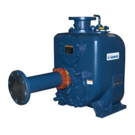
U SERIES PUMP
MODEL
U4A60---B
INCLUDING: /F, /FM
THE GORMAN-RUPP COMPANY D MANSFIELD, OHIO
GORMAN-RUPP OF CANADA LIMITED
ST. THOMAS, ONTARIO, CANADA
D
Printed in U.S.A.
www.gormanrupp.com
E
Copyright by the Gorman-Rupp Company
Advertisement
Table of Contents

Related Manuals for GORMAN-RUPP PUMPS U4A60-B


Summary of Contents for GORMAN-RUPP PUMPS U4A60-B
- Page 1 OM-01862-OB02 November 7, 1986 Rev. E 03/19/03 INSTALLATION, OPERATION, AND MAINTENANCE MANUAL WITH PARTS LIST U SERIES PUMP MODEL U4A60---B INCLUDING: /F, /FM THE GORMAN-RUPP COMPANY D MANSFIELD, OHIO GORMAN-RUPP OF CANADA LIMITED ST. THOMAS, ONTARIO, CANADA Printed in U.S.A. www.gormanrupp.com Copyright by the Gorman-Rupp Company...
- Page 2 TABLE OF CONTENTS INTRODUCTION ..........PAGE I --- 1 SAFETY --- SECTION A .
-
Page 3: Table Of Contents
TABLE OF CONTENTS (continued) TROUBLESHOOTING --- SECTION D ......PAGE D --- 1 PREVENTIVE MAINTENANCE . - Page 4 U SERIES OM -- 01862-- 02 INTRODUCTION Thank You for purchasing a Gorman-Rupp pump. priming centrifugal model. The pump is designed Read this manual carefully to learn how to safely for high-efficiency, self-priming service, and is ca- install and operate your pump. Failure to do so pable of handling most non-volatile , non-corrosive could result in personal injury or damage to the liquids containing specified entrained solids.
- Page 5 U SERIES OM -- 01862 SAFETY --- SECTION A This information applies to U Series ba- not attempt to pump volatile, corrosive, sic pumps. Gorman-Rupp has no con- or flammable materials which may dam- trol over or particular knowledge of the age the pump or endanger personnel as power source which will be used.
- Page 6 OM -- 01862 U SERIES tain that rotation is correct before fully engaging the pump. Use lifting and moving equipment in good repair and with adequate capacity to prevent injuries to personnel or dam- age to equipment. Suction and dis- charge hoses and piping must be re- moved from the pump before lifting.
- Page 7 OUTLINE DRAWING NOTE: OPTIONAL ASA OR DIN DISCHARGE SPOOL FLANGE AVAILABLE Figure 1. Pump Model U4A60-B, Including /F, /FM PREINSTALLATION INSPECTION inspect the pump for damage which may have oc- curred during shipment. Check as follows: The pump assembly was inspected and tested be- fore shipment from the factory.
- Page 8 OM -- 01862 U SERIES proximately 620 pounds (281 kg), not including a. Inspect the pump for cracks, dents, damaged threads, and other obvious damage. the weight of accessories and base. Customer in- stalled equipment such as suction and discharge b.
- Page 9 U SERIES OM -- 01862 Materials the source of the liquid being pumped; if the line slopes down to the pump at any point along the suction run, air pockets will be created. Either pipe or hose maybe used for suction and discharge lines;...
- Page 10 OM -- 01862 U SERIES If there is a liquid flow from an open pipe into the tance equal to at least 3 times the diameter of the sump, the flow should be kept away from the suc- suction pipe. tion inlet because the inflow will carry air down into the sump, and air entering the suction line will re- Suction Line Positioning...
- Page 11 U SERIES OM -- 01862 must be secured against being drawn into With high discharge heads, it is recommended that a throttling valve and a system check valve be in- the pump suction inlet. stalled in the discharge line to protect the pump It is also recommended that pipe unions be in- from excessive shock pressure and reverse rota- stalled at each 90_ elbow in a bypass line to ease...
- Page 12 OM -- 01862 U SERIES tures, and vapor pressure within the When the pump is fully primed, pressure resulting from flow against the valve diaphragm com- pump can cause parts being disen- presses the spring and closes the valve (Figure 4). gaged to be ejected with great force.
- Page 13 U SERIES OM -- 01862 DISCHARGE PIPE CLEAN-OUT COVER INSTALL AIR RELEASE VALVE IN HORIZONTAL POSITION DISCHARGE CHECK VALVE 90_ LONG RADIUS ELBOW SUPPORT PUMP DISCHARGE BRACKET SELF-PRIMING CENTRIFUGAL PUMP BLEED LINE 1” (25,4 MM) DIA. MIN. (CUSTOMER FUR- NISHED) EXTEND 6” SUCTION (152 MM) BELOW LINE...
- Page 14 OM -- 01862 U SERIES When checking alignment, disconnect the power source to ensure that the pump will remain inoperative. Adjusting the alignment in one direction may alter the alignment in another direc- Figure 6B. Aligning Non-Spider tion. check each procedure after altering Type Couplings alignment.
- Page 15 U SERIES OM -- 01862 Do not operate the pump without the guards in place over the rotating parts. Exposed rotating parts can catch cloth- ing, fingers, or tools, causing severe in- jury to personnel. MISALIGNED: MISALIGNED: ALIGNED: SHAFTS SHAFTS SHAFTS PARALLEL AND NOT PARALLEL...
- Page 16 OM -- 01862 U SERIES OPERATION --- SECTION C not prime when dry. extended operation of Review all SAFETY information in Section A. a dry pump will destroy the seal assembly. Follow the instructions on all tags, labels and de- Add liquid to the pump casing when: cals attached to the pump.
- Page 17 OM -- 01862 U SERIES Rotation liquid. If the pump fails to prime within five minutes, stop it and check the suction line for leaks. The correct direction of pump rotation is clockwise After the pump has been primed, partially close the when facing the pump drive shaft.
- Page 18 OM -- 01862 U SERIES Pump Vacuum Check With the pump inoperative, install a vacuum gauge in the system, using pipe dope on the threads. Allow an over-heated pump to com- Block the suction line and start the pump. At oper- pletely cool before servicing.
- Page 19 OM -- 01862 U SERIES remaining liquid that could freeze the pump rotat- Checking bearing temperatures by hand is inaccu- ing parts. If the pump will be idle for more than a rate. Bearing temperatures can be measured ac- few hours, or if it has been pumping liquids con- curately by placing a contact-type thermometer taining a large amount of solids, drain the pump, against the housing.
-
Page 20: Troubleshooting
U SERIES OM -- 01862 TROUBLESHOOTING --- SECTION D Review all SAFETY information in Section A. Before attempting to open or service the pump: 1. Familiarize yourself with this manual. 2. Lock out or disconnect the power source to ensure that the pump will remain inoperative. - Page 21 OM -- 01862 U SERIES TROUBLE POSSIBLE CAUSE PROBABLE REMEDY Air leak in suction line. Correct leak. PUMP STOPS OR FAILS TO DELIVER Lining of suction hose collapsed. Replace suction hose. RATED FLOW OR PRESSURE Leaking or worn seal or pump gasket. Check pump vacuum.
-
Page 22: Preventive Maintenance
U SERIES OM -- 01862 TROUBLE POSSIBLE CAUSE PROBABLE REMEDY EXCESSIVE NOISE Cavitation in pump. Reduce suction lift and/or friction losses in suction line. Record vac- uum and pressure gauge readings and consult local representative or factory. Pumping entrained air. Locate and eliminate source of air bubble. - Page 23 OM -- 01862 U SERIES Preventive Maintenance Schedule Service Interval* Item Daily Weekly Monthly Semi- Annually Annually General Condition (Temperature, Unusual Noises or Vibrations, Cracks, Leaks, Loose Hardware, Etc.) Pump Performance (Gauges, Speed, Flow) Bearing Lubrication Seal Lubrication (And Packing Adjustment, If So Equipped) V-Belts (If So Equipped) Air Release Valve Plunger Rod (If So Equipped)
-
Page 24: Pump Maintenance And Repair
MAINTENANCE AND REPAIR OF THE WEARING PARTS OF THE PUMP WILL MAINTAIN PEAK OPER- ATING PERFORMANCE. STANDARD PERFORMANCE FOR PUMP MODEL U4A60-B, INCLUDING /F AND /FM Based on 70_ F (21_ C) clear water at sea level Contact the Gorman-Rupp Company to verify per- formance or part numbers. - Page 25 OM -- 01862 U SERIES SECTION DRAWING TOP VIEW PRESSURE EQUALIZING PASSAGE Figure 1. Pump Model U4A60---B, Including /F, /FM PAGE E -- 2 MAINTENANCE & REPAIR...
-
Page 26: Parts Lists
OM -- 01862 U SERIES PARTS LIST Pump Model U4A60---B Including /F, /FM (From S/N 860554 up) If your pump serial number is followed by an “N”, your pump is NOT a standard production model. Contact the Gorman-Rupp Company to verify part numbers. ITEM PART NAME PART... - Page 27 OM -- 01862 U SERIES SECTION DRAWING Figure 2. 44163---041 Repair Rotating Assembly PAGE E -- 4 MAINTENANCE & REPAIR...
- Page 28 OM -- 01862 U SERIES PARTS LIST 44163---041 Repair Rotating Assembly ITEM PART NAME PART MAT’L ITEM PART NAME PART MAT’L NUMBER CODE NUMBER CODE SOCKET HD CAPSCREW DM1004S 15991 IMPELLER 38619--- 011 11000 SEAL PLATE O-RING 25152--- 276 --- --- --- SEAL ASSEMBLY 46513--- 151 --- --- ---...
-
Page 29: Pump And Seal Disassembly And Reassembly
OM -- 01862 U SERIES PUMP AND SEAL DISASSEMBLY 1. Familiarize yourself with this man- ual. AND REASSEMBLY 2. Disconnect or lock out the power source to ensure that the pump will Review all SAFETY information in Section A. remain inoperative. 3. -
Page 30: Impeller Removal
U SERIES OM -- 01862 The impeller (1) should be loosened while the rotat- rotating assembly by pulling straight away from the ing assembly is still secured to the pump casing. pump casing. Before loosening the impeller, remove the seal cav- ity drain plug (18) and drain the seal lubricant. -
Page 31: Seal Removal
OM -- 01862 U SERIES Remove the impeller adjusting shims (23); tie and Place a block of wood against the impeller end of tag the shims, or measure and record their thick- the shaft and tap the shaft and assembled bear- ness for ease of reassembly. -
Page 32: Shaft And Bearing Reassembly And Installation
U SERIES OM -- 01862 NOTE housing. Replace the bearings, shaft, or bearing housing if the proper bearing fit is not achieved. Position the inboard bearing (6) on the shaft with the shielded side toward the impeller end of the If bearing replacement is required, remove the out- shaft. -
Page 33: Seal Installation
OM -- 01862 U SERIES tilated area free from excessive heat, sparks, and flame. Read and follow all precautions printed on solvent contain- ers. When installing the shaft and bearings into the bearing bore, push against the outer Clean the seal cavity and shaft with a cloth soaked race. - Page 34 U SERIES OM -- 01862 O-RING ENGAGED WITH SEAL PLATE BORE This seal is not designed for operation at temperatures above 160 F (71 C). Do not use at higher operating temperatures. If the seal plate was removed, install the seal plate gasket (30).
-
Page 35: Impeller Installation
OM -- 01862 U SERIES If necessary to reuse an old seal in an emer- Slide the rotating portion of the seal (consisting of gency, carefully separate the rotating and station- the integral shaft sleeve, spring centering washer, ary seal faces from the bellows retainer and sta- spring, bellows and retainer, and rotating element) tionary seat. -
Page 36: Rotating Assembly Installation
U SERIES OM -- 01862 fore installing the impeller capscrew and washer sembly shims accordingly. (23 and 24). The rotating assembly must be in- stalled in the pump casing in order to torque the im- After the face clearance is set, tighten the hardware peller capscrew. -
Page 37: Final Pump Assembly
OM -- 01862 U SERIES been specified or provided by the Gorman-Rupp ounces (0,6 liters) of SAE No. 30 non-detergent oil, Company. or to a level just below the tapped vented plug hole. Clean and reinstall the vented plug. Maintain the oil Periodically, the valve should be removed for in- at this level. - Page 38 For U.S. and International Warranty Information, Please Visit www.grpumps.com/warranty or call: U.S.: 419−755−1280 International: +1−419−755−1352 For Canadian Warranty Information, Please Visit www.grcanada.com/warranty or call: 519−631−2870 THE GORMAN-RUPP COMPANY D MANSFIELD, OHIO GORMAN-RUPP OF CANADA LIMITED ST. THOMAS, ONTARIO, CANADA...
Need help?
Do you have a question about the U4A60-B and is the answer not in the manual?
Questions and answers