GORMAN-RUPP PUMPS U Series Installation, Operation, And Maintenance Manual With Parts List
Hide thumbs
Also See for U Series:
Table of Contents
Advertisement
Quick Links
C
OM-01864-OB02
July 20, 1990
Rev. D 10/14/02
INSTALLATION, OPERATION,
AND MAINTENANCE MANUAL
WITH PARTS LIST
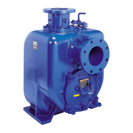
U-SERIES PUMP
MODELS
U6B60---B
INCLUDING: /F, /FM
THE GORMAN-RUPP COMPANY D MANSFIELD, OHIO
GORMAN-RUPP OF CANADA LIMITED
ST. THOMAS, ONTARIO, CANADA
D
Printed in U.S.A.
E
Copyright by the Gorman-Rupp Company
Advertisement
Table of Contents

Related Manuals for GORMAN-RUPP PUMPS U Series


Summary of Contents for GORMAN-RUPP PUMPS U Series
- Page 1 OM-01864-OB02 July 20, 1990 Rev. D 10/14/02 INSTALLATION, OPERATION, AND MAINTENANCE MANUAL WITH PARTS LIST U-SERIES PUMP MODELS U6B60---B INCLUDING: /F, /FM THE GORMAN-RUPP COMPANY D MANSFIELD, OHIO GORMAN-RUPP OF CANADA LIMITED ST. THOMAS, ONTARIO, CANADA Printed in U.S.A. Copyright by the Gorman-Rupp Company...
- Page 2 TABLE OF CONTENTS INTRODUCTION ..........PAGE I --- 1 SAFETY --- SECTION A .
-
Page 3: Table Of Contents
TABLE OF CONTENTS (continued) TROUBLESHOOTING --- SECTION D ......PAGE D --- 1 PREVENTIVE MAINTENANCE . - Page 4 Gorman- to those which could be dangerous to personnel: Rupp pump. This pump is a U Series, semi---open impeller, self- priming centrifugal model with a suction check valve. It is designed for high-efficiency distribution of liquids containing specified entrained solids.
- Page 5 U SERIES OM -- 01864 SAFETY --- SECTION A This information applies to U Series ba- sive, or flammable materials, or any liq- uids which may damage the pump or en- sic pumps. Gorman-Rupp has no con- danger personnel as a result of pump trol over or particular knowledge of the failure.
- Page 6 OM -- 01864 U SERIES Use lifting and moving equipment in good repair and with adequate capacity to prevent injuries to personnel or dam- age to equipment. Suction and dis- charge hoses and piping must be re- moved from the pump before lifting.
- Page 7 U SERIES OM -- 01864 INSTALLATION --- SECTION B Review all SAFETY information in Section A. configuration, and priming must be tailored to the specific application. Since the pressure supplied Since pump installations are seldom identical, this to the pump is critical to performance and safety,...
- Page 8 U SERIES OM -- 01864 PREINSTALLATION INSPECTION POSITIONING PUMP Lifting The pump assembly was inspected and tested be- fore shipment from the factory. Before installation, Use lifting equipment with a capacity of at least inspect the pump for damage which may have oc- 4,920 pounds (2231,7 kg).
- Page 9 U SERIES OM -- 01864 used in suction lines, it must be the rigid-wall, rein- Fittings forced type to prevent collapse under suction. Us- Suction lines should be the same size as the pump ing piping couplings in suction lines is not recom- inlet.
- Page 10 U SERIES OM -- 01864 If it is necessary to position inflow close to the suc- Suction Line Positioning tion inlet, install a baffle between the inflow and the The depth of submergence of the suction line is suction inlet at a distance 1 1/2 times the diameter critical to efficient pump operation.
- Page 11 U SERIES OM -- 01864 In high discharge head applications (more than 30 feet), an excessive amount of liquid may be by- passed and forced back to the wet well under the full working pressure of the pump; this will reduce If the application involves a high discharge overall pumping efficiency.
- Page 12 U SERIES OM -- 01864 AUTOMATIC AIR RELEASE VALVE of liquid to 1 to 5 gallons per minute, until the pump loses its prime or stops. When properly installed and correctly adjusted to the specific hydraulic operating conditions of the...
- Page 13 U SERIES OM -- 01864 DISCHARGE PIPE CLEAN-OUT COVER INSTALL AIR RELEASE VALVE IN HORIZONTAL POSITION DISCHARGE CHECK VALVE 90_ LONG RADIUS ELBOW SUPPORT PUMP DISCHARGE BRACKET SELF-PRIMING CENTRIFUGAL PUMP BLEED LINE 1” (25,4 MM) DIA. MIN. (CUSTOMER FURNISHED) EXTEND 6”...
- Page 14 U SERIES OM -- 01864 When checking alignment, disconnect the power source to ensure that the pump will remain inoperative. Adjusting the alignment in one direction Figure 7. Aligning Non-Spider may alter the alignment in another direc- Type Couplings tion. Check each procedure after altering Check parallel adjustment by laying a straightedge alignment.
- Page 15 U SERIES OM -- 01864 Select pulleys that will match the proper speed ra- tio; overspeeding the pump may damage both pump and power source. Do not operate the pump without the guard in place over the rotating parts. Exposed rotating parts can catch cloth- ing, fingers, or tools, causing severe in- jury to personnel.
- Page 16 OM -- 01864 U SERIES OPERATION --- SECTION C Review all SAFETY information in Section A. Add liquid to the pump casing when: 1. The pump is being put into service for the Follow the instructions on all tags, labels and de- first time.
- Page 17 OM -- 01864 U SERIES Liquid Temperature And Overheating allow the pump to prime, and automatically close after priming is complete (see INSTALLATION for The maximum liquid temperature for this pump is Air Release Valve operation). 160_ F (71_ C). Do not apply it at a higher operat- ing temperature.
- Page 18 OM -- 01864 U SERIES Never introduce air or steam pressure into the After stopping the pump, disconnect the power pump casing or piping to remove a blockage. This source to ensure that the pump will remain inop- could result in personal injury or damage to the erative.
-
Page 19: Troubleshooting
OM -- 01864 U SERIES TROUBLESHOOTING --- SECTION D Review all SAFETY information in Section A. Before attempting to open or service the pump: 1. Familiarize yourself with this manual. 2. Lock out or disconnect the power source to ensure that the pump will remain inoperative. - Page 20 OM -- 01864 U SERIES TROUBLE POSSIBLE CAUSE PROBABLE REMEDY PUMP STOPS OR Check installation and correct sub- Suction intake not submerged at FAILS TO DELIVER mergence as needed. proper level or sump too small. RATED FLOW OR PRESSURE (cont.) Impeller or other wearing parts worn Replace worn or damaged parts.
-
Page 21: Preventive Maintenance
OM -- 01864 U SERIES TROUBLE POSSIBLE CAUSE PROBABLE REMEDY BEARINGS RUN Bearing temperature is high, but Check bearing temperature regu- TOO HOT within limits. larly to monitor any increase. Low or incorrect lubricant. Check for proper type and level of lubricant. - Page 22 OM -- 01864 U SERIES Preventive Maintenance Schedule Service Interval* Item Daily Weekly Monthly Semi- Annually Annually General Condition (Temperature, Unusual Noises or Vibrations, Cracks, Leaks, Loose Hardware, Etc.) Pump Performance (Gauges, Speed, Flow) Bearing Lubrication Seal Lubrication (And Packing Adjustment,...
-
Page 23: Pump Maintenance And Repair
OM -- 01864 U SERIES PUMP MAINTENANCE AND REPAIR --- SECTION E MAINTENANCE AND REPAIR OF THE WEARING PARTS OF THE PUMP WILL MAINTAIN PEAK OPER- ATING PERFORMANCE. STANDARD PERFORMANCE FOR PUMP MODEL U6B60-B Based on 70_ F (21_ C) clear water at sea level Contact the Gorman-Rupp Company to verify per- formance or part numbers. - Page 24 OM -- 01864 U SERIES SECTION DRAWING Figure 1. Pump Model U6B60---B PAGE E -- 2 MAINTENANCE & REPAIR...
-
Page 25: Parts Lists
OM -- 01864 U SERIES PARTS LIST Pump Model U6B60---B (From S/N 948005 up) If your pump serial number is followed by an “N”, your pump is NOT a standard production model. Contact the Gorman-Rupp Company to verify part numbers. - Page 26 OM -- 01864 U SERIES SECTION DRAWING Figure 2. 44163---133 Repair Rotating Assembly PAGE E -- 4 MAINTENANCE & REPAIR...
- Page 27 OM -- 01864 U SERIES PARTS LIST 44163---133 Repair Rotating Assembly ITEM PART MAT’L PART NAME NUMBER CODE IMPELLER 38618---016 11010 SEAL ASSEMBLY 46513---154 --- --- --- SEAL PLATE 38272---408 10010 SEAL PLATE GSKT 12350G 20000 INBOARD OIL SEAL S1917...
-
Page 28: Pump And Seal Disassembly And Reassembly
OM -- 01864 U SERIES PUMP AND SEAL DISASSEMBLY 3. Allow the pump to completely cool if overheated. AND REASSEMBLY 4. Check the temperature before opening any covers, plates, or Review all SAFETY information in Section A. plugs. 5. Close the suction and discharge Follow the instructions on all tags, label and de- valves. -
Page 29: Rotating Assembly Removal
U SERIES OM -- 01864 Individual parts are not sold separately. With the impeller rotation still blocked, see Figure 3 and use a long piece of heavy bar stock to pry against the arm of the lathe dog in a counterclock-... -
Page 30: Impeller Removal
OM -- 01864 U SERIES ADD PIPE AS REQUIRED Figure 4. Rotating Assembly Removal With Tool Impeller Removal If no further disassembly is required, refer to Seal Installation. (Figure 2) Shaft and Bearing Removal and Disassembly Unscrew the impeller from the shaft in a counter- (Figure 2) clockwise direction (when facing the impeller). -
Page 31: Shaft And Bearing Reassembly And Installation
U SERIES OM -- 01864 and use a bearing puller to remove the inboard and outboard bearings from the shaft. Shaft and Bearing Reassembly and Installation To prevent damage during removal from the shaft, it is recommended that bearings (Figure 2) be cleaned and inspected in place. -
Page 32: Seal Reassembly And Installation
OM -- 01864 U SERIES NOTE Position the inboard bearing (9) on the shaft as indi- cated by the following illustration. BALL LOADING BALL LOADING GROOVE POSITIONED GROOVE POSITIONED TOWARD IMPELLER AWAY FROM IMPELLER LOADING LOADING GROOVE GROOVE DIRECTION OF... - Page 33 U SERIES OM -- 01864 tilated area free from excessive heat, sparks, and flame. Read and follow all precautions printed on solvent contain- ers. A new seal assembly should be installed any time the old seal is removed from the Clean the seal cavity and shaft with a cloth soaked pump.
- Page 34 OM -- 01864 U SERIES When installing a new cartridge seal assembly, shaft shoulder. Continue to screw the impeller onto remove the seal from the container, and remove the shaft until the impeller, shims, and sleeve are the mylar storage tabs from between the seal fully seated against the shaft shoulder (see Figure faces.
-
Page 35: Impeller Installation And Adjustment
U SERIES OM -- 01864 rection of the impeller when checking this clear- ance. NOTE Do not attempt to separate the rotating If the rotating assembly has been installed in the portion of the seal from the shaft sleeve pump casing, this clearance may be measured by when reusing an old seal. -
Page 36: Suction Check Valve Installation
OM -- 01864 U SERIES in the direction of the impeller when checking Replace the back cover O-ring (35), and lubricate it this clearance. After the impeller binds, add .004 with a generous amount of No. 2 grease. Clean any inch of shims to each shim set. -
Page 37: Bearings
U SERIES OM -- 01864 ounces (2,7 liters) of SAE No. 30 non-detergent oil ounces (0,95 liters) of clean oil. Change the oil (so it is above the level of the internal casting). more frequently if the pump is operated continu- Clean and reinstall the vented plug. - Page 38 For U.S. and International Warranty Information, Please Visit www.grpumps.com/warranty or call: U.S.: 419−755−1280 International: +1−419−755−1352 For Canadian Warranty Information, Please Visit www.grcanada.com/warranty or call: 519−631−2870 THE GORMAN-RUPP COMPANY D MANSFIELD, OHIO GORMAN-RUPP OF CANADA LIMITED ST. THOMAS, ONTARIO, CANADA...
Need help?
Do you have a question about the U Series and is the answer not in the manual?
Questions and answers