
Related Manuals for laguna Revo 18


Summary of Contents for laguna Revo 18
- Page 1 PRECISION WOODWORKING Revo 18|36 Lathe Owner's Manual MLAREVO 1836-110-150 256540 MLAREVO 1836-220 2/19/2021...
- Page 2 Laguna takes pride in our products and stands behind them with continuing service and support for our customers. Your Laguna machine was designed to bring a new dimension of productivity to your shop. Before using your machine for the first time, learn how to use it. This manual covers a step-by-step process of assembly and machine operation.
-
Page 3: Table Of Contents
Revo 18|36 Lathe Table of Contents Safety ................4 Electrical Saftey ............10 Specifications .............. 14 Machine Overview ............15 Setup ................21 Videos ..............21 Placement & Unboxing ........23 Inventory List ............27 Assembling the Lathe ......... 29 Standard Accessories ........ -
Page 4: Safety
Revo 18|36 Lathe \ Safety Safety Read and understand all warnings and operation instructions before using any tool or equipment. Always follow basic safety precautions to reduce the risk of personal injury. Improper operation, maintenance or modification of tools or equipment could result in serious injury and property damage. There are certain applications for which tools and equipment are designed. - Page 5 Revo 18|36 Lathe \ Safety Important Safety Instructions Read and understand all warnings and operating instructions before using this equipment. Failure to follow all instructions listed below, may result in electric shock, fire, and/or serious personal injury or property damage.
- Page 6 Revo 18|36 Lathe \ Safety e) Rough out work piece before installing on faceplate. f) Do not mount split work piece or one containing a knot. g) Use lowest speed when starting new work piece. 1. KEEP GUARDS IN PLACE and in working order.
- Page 7 Revo 18|36 Lathe \ Safety 20. DIRECTION OF FEED. Feed work into a blade or cutter against the direction of rotation of the blade or cutter only. 21. NEVER LEAVE TOOL RUNNING UNATTENDED. TURN POWER OFF. Don't leave tool until it comes to a complete stop.
- Page 8 Revo 18|36 Lathe \ Safety 12. IMMOBILISEZ VOTRE TRAVAIL. lisez des serres ou un étau pour immobiliser votre travail lorsque c'est possible. C'est plus sécuritaire que d'u liser votre main, et ça permet de libérer vos deux mains pour opérer l confortablement.
- Page 9 Revo 18|36 Lathe \ Safety Locking the Lathe It is strongly recommended that the lathe is never be left unattended in the unlocked condition. To lock the machine it is recommended that a cover (not supplied) is made to lock the control panel. We have supplied two concepts for locking the panel (see below).
-
Page 10: Electrical Saftey
Revo 18|36 Lathe \ Electrical Saftey Electrical Saftey Power Connections A separate electrical circuit should be used for each machine. This circuit should not be less than the wiring listed below and should be protected with an appropriate circuit breaker based on the total running and start-up amperage's (listed below). - Page 11 Revo 18|36 Lathe \ Electrical Saftey If this information is different than what is stated on the Motor Specification Plate - omit this information. It is possible that the documentation is outdated to a machine change - such as a different motor. Always check the motor plate prior to any wiring.
- Page 12 Revo 18|36 Lathe \ Electrical Saftey grounding conductor and a grounding plug. The plug must be plugged into a matching outlet that is properly installed and grounded in accordance with all local codes and ordinances. Do not modify the plug provided - if it will not fit the outlet, have the proper outlet installed by a qualified electrician.
- Page 13 Revo 18|36 Lathe \ Electrical Saftey Extension Cords Use proper extension cords. Make sure your extension cord is in good condition and is a 3- wire extension cord which has a 3-prong grounding type plug and matching receptacle which will accept the machine’s plug.
-
Page 14: Specifications
Revo 18|36 Lathe \ Specifications Specifications MLAREVO 1836-220 MLAREVO 1836-110-150 Motor Induction,1725RPM, 2 HP 220V Induction,1725RPM, 1.5 HP 110V Voltage 220v 60hz single phase input, 3 phase 110v 60hz single phase input 3 phase output output Recommended breaker 15 amp... -
Page 15: Machine Overview
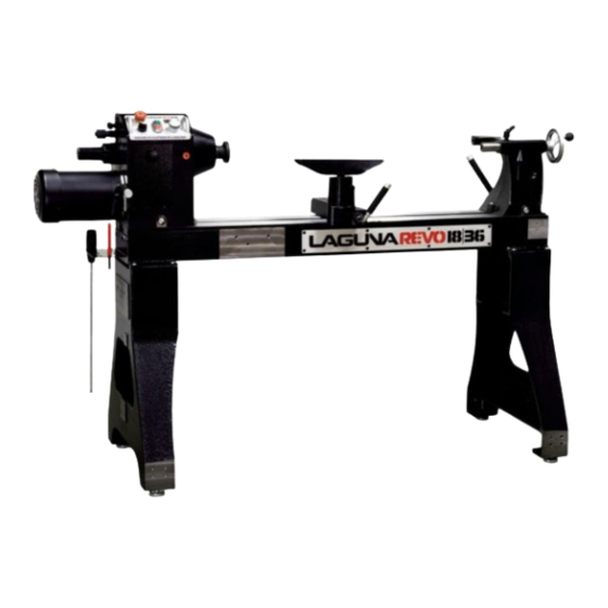
Revo 18|36 Lathe \ Machine Overview Machine Overview Revo 18|36 Lathe This machine is designed to give you years of safe service. Read this owner's manual in its entirety before assembly or use. The lathe consists of a number of major parts, which are discussed in this manual. Take the time to read this section and become familiar with the machine. - Page 16 Revo 18|36 Lathe \ Machine Overview Lathe Bed The bed is a machined heavy steel welded construction. Lathe Legs The Legs are cast iron, and their heavy construction gives the machine a low center of gravity and ensures that it is very stable. The legs are supplied with adjustable feet to allow the machine to be leveled.
- Page 17 Revo 18|36 Lathe \ Machine Overview Tail Stock The tail stock is of cast iron construction, and the spindle has a travel of 4 1/2 in. It can accommodate centers and other tools which have a number 2 Morse Taper. The tail stock can be moved to any position on the lathe bed and locked to suit the job at hand.
- Page 18 Revo 18|36 Lathe \ Machine Overview Tool Rest The tool rest can be moved to any position on the lathe bed and locked to suit the job at hand. The tool rest has a tall profile to allow the bowl turner to turn steep angles. The leading edge is made from 6mm hardened steel.
- Page 19 Revo 18|36 Lathe \ Machine Overview Tool Storage A tool storage bracket which can be mounted on either leg. Left of Bed Storage Lathe Controls Emergency stop button The emergency stop button will lock in the OFF position when fully depressed. To reset it, twist clockwise and it will pop out.
- Page 20 Revo 18|36 Lathe \ Machine Overview Start / Stop buttons. The start / stop buttons start the motor and the rotation of the spindle. Speed display. The speed display shows the RPM of the spindle. Variable speed adjustment knob. The Variable speed adjustment knob adjusts the spindle speed.
-
Page 21: Setup
Setup Setup Overview (MUST READ) When setting up your Revo 18|36 Lathe, please take a moment to read this overview prior to starting. The machine comes mostly assembled. You will have to assemble the legs, headstock, tailstock, tool storage and the tool rest to the bed of the machine. NOTICE! It is recommended that the head stock, tool rest and tailstock be removed from the bed of the lathe to ease assembly (Covered later in the manual). - Page 22 Revo 18|36 Lathe \ Setup Videos REVO 1836 Lathe Setup - Install Standard REVO 1836 Lathe Setup - Mounting The Lights - Accesorries - Part 5 Part 6 REVO 1836 Lathe Setup - Installing The REVO 1836 Lathe Setup - Install The Vacuum...
-
Page 23: Placement & Unboxing
NOTICE! All shipping damage must be noted upon delivery and signed by the owner and the delivery driver. If you find any damaged items in your package, you must contact Laguna Tools to file a complaint. In order to return damaged goods under the limited warranty to Laguna Tools, Inc., you MUST have the original packaging. - Page 24 Revo 18|36 Lathe \ Setup Placement & Unboxing Placement Before you remove your machine from the packaging, select the area where you will use your machine. There are no hard and fast rules for its location, but below are a few guidelines: 1.
- Page 25 Revo 18|36 Lathe \ Setup Placement & Unboxing 2. Open the box and remove the parts sent with the lathe including the first leg. NOTICE! The legs are heavy and caution must be exercised. They are cast iron and if dropped they will break.
- Page 26 Revo 18|36 Lathe \ Setup Placement & Unboxing 6. Remove the tailstock, headstock, and banjo. NOTICE! The headstock and tailstock can not be removed if they are locked to the bed. Disengage the lock handle prior to removal. NOTICE! Even if you lifted the lathe out of the box with a lift, please remove everything from the bed.
-
Page 27: Inventory List
Revo 18|36 Lathe \ Setup Inventory List Inventory List The following depicts items shipped with your machine. Before assembling, ensure that you have received all parts shown below. Machine parts should arrive sealed in plastic bags. Remove parts from plastic bags before laying them out to inventory them. - Page 28 Revo 18|36 Lathe \ Setup Inventory List Description PACKAGING Drive Center Upper Packaging Quill Knob Upper Packaging Faceplate Wrench Upper Packaging Knock Out Rod Upper Packaging Adjustable Feet Upper Packaging Tailstock Bracket & Hardware Upper Packaging Headstock Bracket & Upper Packaging...
-
Page 29: Assembling The Lathe
Revo 18|36 Lathe \ Setup Assembling the Lathe Assembling the Lathe Quick Reference Guide Add. Required Tools: Allen Wrench · Hex Wrench · Troubleshooting/Tips: The legs are not unique to the right or left side. If you purchased the riser blocks, install them now. - Page 30 Revo 18|36 Lathe \ Setup Assembling the Lathe 3. Lift the legs to the vertical position and lower them onto the bed. Secure with the 8 fixing screws provided. 4. Very carefully flip the lathe to the upright position. Do not slam the legs onto concrete - the cast iron will crack.
- Page 31 Revo 18|36 Lathe \ Setup Assembling the Lathe 5. Carefully move the lathe away form the table. 6. Fine tune the leveling feet so the lathe bed is level. Tailstock, Headstock, Banjo Parts Needed Description Installation Location Headstock TailStock NOTICE! For lathes with serial...
- Page 32 Revo 18|36 Lathe \ Setup Assembling the Lathe Underside of bed Banjo Post hole & Tool Rest post Cam Lock Washer; Headstock, Tailstock, Banjo NOTICE! If it is discovered that the tool rest post does not stay in place when using, it is because of a lubricant within the clamp (banjo post hole and tool rest post).
- Page 33 Revo 18|36 Lathe \ Setup Assembling the Lathe 3. Install the Headstock. At least two people will be needed to perform this step. 4. Re-install the Stops to prevent the headstock and tailstock from coming off the bed. The 1836 Lathe is now assembled.
-
Page 34: Standard Accessories
Revo 18|36 Lathe \ Setup Standard Accessories Standard Accessories Quick Reference Guide Add. Required Tools: Included wrenches · Allen Wrench · Troubleshooting/Tips: Go through each installation and remove to familiarize proper procedure. Installing the Faceplate Parts Needed Description Installation Location... - Page 35 Revo 18|36 Lathe \ Setup Standard Accessories Installing the Driver (Spur) Center Parts Needed Description Installation Location Drive Center Headstock Knock Out Rod Upper Packaging Ensure that the bore of the head stock is clean. The drive center has a number No. 2 Morse Taper that ·...
- Page 36 Revo 18|36 Lathe \ Setup Standard Accessories Installing the Live (Rotating) Center Parts Needed Description Installation Location Rotating Center Tailstock Ensure that the bore of the tail stock is clean. The rotating center has a number 2 Morse Taper that fits ·...
- Page 37 Revo 18|36 Lathe \ Setup Standard Accessories Installing the tool rack Parts Needed Description Installation Location Tool Rack The Tools rack can be installed on any of the mounting locations, and in the upside down position (higher) NOTICE! If installing in the front position, the banjo lock may interfere. The intended location shown below...
-
Page 38: Adjustments
Revo 18|36 Lathe \ Adjustments Adjustments The machine is shipped perfectly adjusted. However during transit, some adjustments could be tweaked. If one is found, follow these guides to resolve. If you have any doubt about the described procedure, seek professional assistance. Do not attempt any procedure that you feel is unsafe, or that you do not have the physical capability of achieving. - Page 39 Revo 18|36 Lathe \ Adjustments Indexing the Spindle Indexing System Do not turn the machine on with the indexing or spindle lock engaged. Indexing is a method of splitting 360 degrees into X parts. It is very useful to have for forming spirals, channels, or notches on a work piece.
- Page 40 Revo 18|36 Lathe \ Adjustments Side to Side Stock Adjustments Tail Stock Loosen the clamp handle on the tailstock and check for side movement. If it is excessive, Insert an Allen key into the adjusting screw and tighten. NOTICE! By rotating the adjustment screw, it moves into the adjusting slot which opens and removes the excessive clearance between the tailstock and the bed.
- Page 41 Revo 18|36 Lathe \ Adjustments Center to Center Adjustment Center Points Aligned NOTICE! For Lathes with machine serial number 20074159 and later,or newer, please use the precise position adjustment to further dial in center to center alignment. NOTICE! The slide clearance of the headstock and the tailstock must be checked and adjusted should it be needed prior to adjusting the center point alignment.
- Page 42 Revo 18|36 Lathe \ Adjustments For Lathes With Precise Year 2020 and new 1836 lathes are equipped with a precise position function that allows you to ensure center to center contact between Position the spindle and quill. The adjustment is simple.
-
Page 43: Maintenance
Revo 18|36 Lathe \ Maintenance Maintenance General Keep your machine clean. At the end of each day, clean the machine. Wood contains moisture, and if sawdust or wood chips are not removed they will cause rust. In general, we recommend that you only use a Teflon-based lubricant on the lathe. Regular oil attracts dust and dirt. -
Page 44: Troubleshooting
Revo 18|36 Lathe \ Troubleshooting Troubleshooting Lathe will not start. Motor overheats. 1. Check that the start switch is in the correct The motor is designed to run hot, but should it position. overheat it has an internal thermal overload protector 2. -
Page 45: Wiring
Revo 18|36 Lathe \ Wiring Wiring Review Electrical Safety prior to any wiring procedures. 220V 110V SENSOR EMERGENCY STOP 110V 110V 220V 220V FWD/REV Make sure the black pin SWITCH is inserted into the correct SWITCH POTENTIOMETER position for either 110V or 220V... -
Page 46: Replacement Parts Diagram
Revo 18|36 Lathe \ Replacement Parts Diagram Replacement Parts Diagram Bed, Headstock, Drive Center... - Page 47 Revo 18|36 Lathe \ Replacement Parts Diagram Bed, Banjo, Tail Stock, Live Center...
-
Page 48: Replacement Parts Table
Replacement Parts Table Index Part Number Item Description Specification PLAREVO1836-101 PLAREVO1836-102 Spindle Pulley PLAREVO1836-103 Spring PLAREVO1836-104 Spindle Lock Plunger PLAREVO1836-105 Locking Collar PLAREVO1836-106 Bearing Nut PLAREVO1836-107 Door PLAREVO1836-108A Tailstock PLAREVO1836-109 Motor Pulley PLAREVO1836-110 Motor Plate PLAREVO1836-111 Headstock Locking Handle PLAREVO1836-112A Headstock PLAREVO1836-113 3"... - Page 49 Index Part Number Item Description Specification PLAREVO1836-133 Index Bolt PLAREVO1836-134 Index Knob PLAREVO1836-135 Tool Rest Support Base PLAREVO1836-136 Cord Holder PLAREVO1836-137 Tool Rest Locking Handle PLAREVO1836-138 12" Tool Rest PLAREVO1836-139 PLAREVO1836-140A Lock Handle PLAREVO1836-141 Handwheel PLAREVO1836-142A Quill PLAREVO1836-143 Tailstock Locking Handle PLAREVO1836-144 Live Center Assembly PLAREVO1836-145...
- Page 50 Index Part Number Item Description Specification PLAREVO1836-170 ON/ OFF Switch PLAREVO1836-171A Emergency Stop PLAREVO1836-172 Spacer PLAREVO1836-173A Fwd/Rev Switch 480BS-117 Screw M4x6 PLAREVO1836-175 Ball Bearing 6205LLU PLAREVO1836-176 Ball Bearing 6207LLU PLAREVO1836-177 Pillar PLAREVO1836-178 Index Label PLAREVO1836-179 Index Indicator PLAREVO1836-180 Power Cord 220V PLAREVO1836-110-150-180 Power Cord 110V PLAREVO1836-181...
- Page 51 Index Part Number Item Description Specification PLAREVO1836-1105 Flat Head Socket Screw M3x8 PLAREVO1836-1106 Phillips Flat Head Screw M6x16 PLAREVO1836-1107 Screw M3x4 PLAREVO1836-1108 Motor Cord PLAREVO1836-1109 Flat Washer D3xD8x1t PLAREVO1836-1110 Nylon Insert Lock Nut M18x2.5 PLAREVO1836-1111 Hex Nut 3/8-16UNC PLAREVO1836-1112 Flat Washer D10xD23x2t PLAREVO1836-1113 Flat Washer...
- Page 52 Index Part Number Item Description Specification PLAREVO1836-1141 Socket Flat Head Screw M3x8 PLAREVO1836-1142 Cord Holder PLAREVO1836-1143 O-Ring PLAREVO1836-1144 Speed Label PLAREVO1836-1145 PLAREVO1836-1146 Socket Head Button Screw 1/4-20UNCx3/8" PLAREVO1836-1147 Headstock Bracket PLAREVO1836-1148 Socket Head Cap Screw 3/8-16UNCx1-1/4" PLAREVO1836-1149 Tailstock Bracket PLAREVO1836-1150 Socket Head Cap Screw 3/8-16UNCx3/4"...
-
Page 53: Warranty
Laguna Tools®. All shipping related claims for loss or damaged goods must be made to Laguna Tools within twenty-four hours of delivery. - Page 54 Minnesota: 5250 West 74th St, Edina, MN 55439, U.S.A Phone: +1-949-474-1200 DAKE CORPORATION 724 Robbins Road, Grand Haven, MI 49417, United States +1-800-937-3253 LAGUNA EUROPE Walker Rd, Bardon Hill, Coalville LE67 1TU, United Kingdom. Phone: +44-1530-516921 © 2020 Laguna Tools...
Need help?
Do you have a question about the Revo 18 and is the answer not in the manual?
Questions and answers