Table of Contents
Advertisement
Quick Links
Advertisement
Table of Contents

Related Manuals for laguna REVO 15 24


Summary of Contents for laguna REVO 15 24
- Page 1 Laguna REVO 15|24 Woodturning Lathe Owner’s Manual Original Publication Date: 12/11209 SKU: MLAREVO1524110 PID: 415241 Laguna Tools® All rights reserved. 2072 Alton Parkway Irvine, CA 92606 U.S.A. Service: +1 (949) 474-1200 or email customerservice@lagunatools.com lagunatools.com...
- Page 2 Laguna takes pride in our products and stands behind them with continuing service and support for our customers. Your Laguna machine was designed to bring a new dimension of productivity to your shop. Before using your machine for the first time, learn how to use it. This manual covers a step-by-step process of assembly and machine operation.
-
Page 3: Table Of Contents
Table of Contents Table of Contents Table of Contents .................................. 2 Warranty & Support ................................3 Registration ......................................3 Who Is Covered? ....................................3 What Is Covered ....................................3 Warranty Limitations ................................... 3 Length of Warranty ..................................... 3 Shipping Damage ....................................3 Safety ...................................... -
Page 4: Warranty & Support
2 Year – New purchases through authorized dealers. proof of purchase. 1 Year – New purchases directly from Laguna Tools. What Is Covered 1 Year – Blades and Accessories Any part, determined by Laguna Tools®, to have a... -
Page 5: Safety
Safety Safety Read and understand all warnings and operation instructions before using any tool or equipment. Always follow basic safety precautions to reduce the risk of personal injury. Improper operation, maintenance or modification of tools or equipment could result in serious injury and property damage. There are certain applications for which tools and equipment are designed. -
Page 6: Manufacture Lathe Safety Rules
Safety Manufacture Lathe Safety Rules WARNING! For Your Own Safety Read Instruction 12. SECURE WORK. Use clamps or a vise to hold the Manual before Operating Lathe work when practical. It's safer than using your hand (a) Wear eye protection. and it frees both hands to operate the tool. - Page 7 Safety ne résistent pas aux impacts et qu'elles ne sont pas (g) U liser la vitesse la plus lente au démarrage d'une homologuées à re de lune es de sécurité. nouvelle pièce. 12. IMMOBILISEZ VOTRE TRAVAIL. lisez des serres ou RÈGLES DE L'OPÉRATEUR un étau pour immobiliser votre travail lorsque c'est possible.
- Page 8 Safety properly grounded outlet is not available. The TABLE A temporary adapter should be used only until a Ampere Rating Volts Total length of cord in feet properly grounded outlet can be installed by a qualified electrician. This adapter is not permitted in Canada.
- Page 9 Your risk of exposure varies, depending on how often Fig L006 - Method of locking the Laguna Revo Lathe. (1) you do this type of work. To reduce your exposure to Constructed 3 side box with padlock holes. (2) Padlocks.
-
Page 10: Specifications
Specifications Specifications LAGUNA REVO 15Ι24 WOODTURNING LATHE SKU ............... MLAREVO1524110 MPN .................... 415241 PID: ..................... 415241 Package Dimensions (W x L x H) ..... L51.6" W22" H21.9" PRODUCT ASSEMBLED DIMENSIONS High (W x L x H) ..............................L52.4" W19.9" H55.9"... - Page 11 Specifications MATERIALS Bed ........................................Steel Head/ Tail Stock ..................................Cast Iron Legs .............................. Cast Iron Combined with Steel Tube Tool Rest ....................................1045 Steel Tool Rest Contact Rod ........................6mm (DIA) Hardened 1045 Steel Banjo ......................................Cast Iron FEATURES Spring Loaded Spindle Lock ..............................Standard Outboard Turning ..................................
-
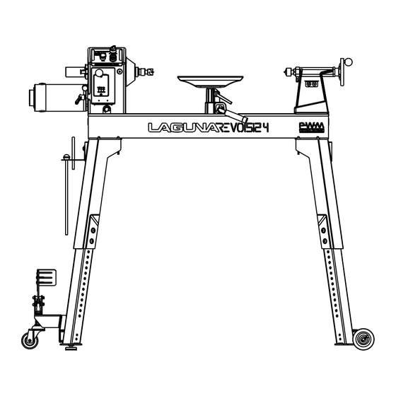
Page 12: Dimensions
Dimensions Dimensions General 19.9" (506.4) 52.4" (1330.7) 18.1" (459.5) 50.6" (1284.1) -
Page 13: Optional Expansion Set
Dimensions OPTIONAL Expansion Set 44" (1117.6) 24" (609.6) 20" (508) 64.1" (1628) 20" (508) -
Page 14: Optional Mobility Kit
Dimensions OPTIONAL Mobility Kit 64.7" (1643.7) 24.4" (618.5) 60.9" (1546.7) 24.4" (618.5) -
Page 15: Set Up
Set Up Set Up Receiving It is likely that your machine will be delivered by a third party. Before unboxing, be sure to inspect the packaging and shipping documents supplied by the driver. Ensure that there is no visible damage to the shipment. If any damage has occurred because of shipment, note the damage on the bill of lading or refuse the shipment. -
Page 16: Lathe Assembly
Set Up Lathe Assembly INDEX ..PART NUMBER ........ DESCRIPTION ........SPECIFICATION ....QTY 21 ....415241-121 ...........Flat Washer ..........D10xD23x2t ......16 68 ....415241-168 ...........Bed ........................1 76 ....PLAREVO1216-174 ......Stop Bolt ......................3 77 ....415241-177 ...........Tailstock Locking Handle ................1 79 .... - Page 17 Set Up Locate the leveling feet from the carton. Install on all four legs to a finger tight position. You will further adjust the legs later to level the bed. Step 2 – Fasten Legs to Stand Body Locate the hardware, select an adequate height for lathe operation, bolt the four legs to stand bodies Floo r to Spind le Center 51"...
- Page 18 Set Up Step 3 – Attach the Tool Shelf Locate the Tool Shelf from the carton and bolt it onto the stand body. Step 4 – Bolt the bed to the assembled legs The lathe will have the safety stops on each end of the bed upon shipment. Please remove the safety stop, headstock, banjo, and tailstock from the bed prior to bolting the bed to the stand.
- Page 19 Set Up Remove Head Stock Remove Banjo Remove Tail Stock Locate the nuts and bolts and bolt down the bed to the legs It is probably easiest to put the bed on the floor (protected with cardboard) and then install each leg. Once installed, carful flip the lathe up-wright.
-
Page 20: Optional Expansion Set
Set Up OPTIONAL Expansion Set INDEX ..PART NUMBER ........ DESCRIPTION ........SPECIFICATION ....QTY 1 ....PLAREVO1836-301 ......20" Bed Extension .................... 1 2 ....PLAREVO1216-174 ......Stop Bolt ......................1 3 ....PLAREVO1836-303 ......Socket Head Button Screw ....... 3/8-16UNCx1" ......3 4 .... -
Page 21: Optional Mobility Kit
Set Up OPTIONAL Mobility Kit Rear Wheel Assembly Front Wheel Assembly... - Page 22 Set Up INDEX ..PART NUMBER ........ DESCRIPTION ........SPECIFICATION ....QTY 1 ....PBAND1412-175-6-1 ......Rod ........................1 2 ....PBAND1412-175-6-2 ......Flat Washer ..........1/4" ..........6 3 ....PBAND1412-175-6-3 ......Socket Head Cap Screw ......1/4"-20UNCx1-3/4"..... 2 4 ....PBAND1412-175-6-4 ......Socket Head Button Screw ....... 5/16"-18UNCx1/2" ...... 2 5 ....
- Page 23 Set Up Step 1 - Install the Slide Brackets Place two bolts (index 33, 5/16-18UNCx3") in each leg, with one washer (index 34) for each bolt. Install the four (index 34) slide brackets to the four wheels. Thread the bolts directly into the slide brackets. Step 2 - Install the rear wheel bracket Install the rear wheel bracket (index 30) the left or right of the lathe using four bolts (index 33, 5/16-18UNCx3"), with two washers (index 38) and one nut (index 32) for each bolt.
- Page 24 Set Up Step 3 – Remove the leveling feet (only on the rear wheel side) Place a support underneath the lathe to prop up and access the leveling feet for removal. Remove both leveling feet. Move the support such that there is access to the rear wheel bracket. Step 4 –...
- Page 25 Set Up Step 5 – Install the Front Wheel Assembly Start by organizing the needed parts and proceed to mount the two other side brackets if you have not done so yet. Place the front wheel bracket (29) on the slide brackets. Drop in the four bolts with one washer before each bolt, and then another washer before the nut, like this: Tighten all hardware.
- Page 26 Set Up Step 5 – Install the Front Wheel Assembly Sandwich the spring between the wheel and the foot lever prior to installing to the front wheel assembly. Screw on the wheel Raise the Lever to force the wheel to the most upward position. Mount the wheel to the bracket with the four screws (27) and four washers (index 5) Finished assemblies:...
-
Page 27: Adjustments
Adjustments Adjustments The 1520 Lathe is equipped with a precise position function that allows you to ensure center to center contact between the spindle and quill. The adjustment is simple. Loosen the four Allen screws. Lock down the tailstock. Lock quill Adjust center to center alignment Fasten the four Allen screws. -
Page 28: Maintenance
Maintenance Maintenance Never perform and setup, maintenance or adjustments with the machine connected to the power source! If you have any doubt about the described procedure, seek professional assistance. Do not attempt any procedure that you feel is unsafe, or that you do not have the physical capability of achieving. When removing banding, extreme caution must be used as the banding will spring when cut. - Page 29 Maintenance Err1:Over-current mode Release the Motor work fail mode steps: • If the operating current of the motor exceeds 18 Amps Press the stop button to release the Motor work for 30 seconds, the control board goes into Over-current fail mode. •...
-
Page 30: Wiring
Wiring Wiring VOLTAGE. Before connecting this tool to a power supply (receptacle, outlet, etc.) make sure that the voltage supplied is the same that is specified on the nameplate of the tool. IF IN DOUBT, DO NOT PLUG IN THE MACHINE. Using this tool with a voltage different than that stated on the nameplate can damage the electrical components of this machine and any such damage will not be covered by a warranty. -
Page 31: Parts
Parts Parts Never perform and setup, maintenance or adjustments with the machine connected to the power source! Only use authentic Laguna Tools parts for replacements. Customer Support: (949)-474-1200 or customerservice@lagunatools.com HeadStock... -
Page 32: Tailstock, Banjo, Tool Rest
Parts Tailstock, Banjo, Tool Rest... -
Page 33: Bed & Leg Assembly
Parts Bed & Leg Assembly... -
Page 34: Parts Table
Parts Parts Table INDEX ..PART NUMBER ........ DESCRIPTION ........SPECIFICATION ....QTY 1 ....415241-101 ...........Headstock ......................1 2 ....415241-102 ...........Spindle ......................1 3 ....PLAREVO1216-109 ......Magnetic Ring ....................1 4 ....PLAREVO1216-113 ......Spindle Pulley ....................1 5 .... - Page 35 Parts 49 ....PLAREVO1836-1128 ......Spacer ......................2 50 ....PLAREVO1836-1127 ......Screw ............M3x12 ........2 51 ....PLAREVO1836-189 ......E-Ring ............E15 ..........4 52 ....PLAREVO1836-117 ......Knob ......................... 1 53 ....PLAREVO1836-193 ......Hex Cap Screw ........... 3/8-16UNCx1/2" ....... 1 54 ....
- Page 36 Parts 102 ....PLAREVO1216-138 ......O-Ring ............P22 ..........1 103 ....415241-1103 ........Poly- V Belt ..........PJ6-180........1 104 ....PLAREVO1836-1136 ......Handle, Faceplate ................... 1 105 ....PLAREVO1836-1112 ......Flat Washer ..........D10xD23x2t ......8 106 ....415241-1106 ........Leveling Foot ....................4 107 ....
-
Page 37: Optional Wheel System
Parts OPTIONAL Wheel System INDEX ..PART NUMBER ........ DESCRIPTION ........SPECIFICATION ....QTY 1 ....PBAND1412-175-6-1 ......Rod ........................1 2 ....PBAND1412-175-6-2 ......Flat Washer ..........1/4" ..........6 3 ....PBAND1412-175-6-3 ......Socket Head Cap Screw ......1/4"-20UNCx1-3/4"..... 2 4 .... - Page 38 Parts 7 ....PBAND1412-175-6-7 ......Fixed Plate ......................1 8 ....PBAND1412-175-6-8 ......Wheel Bracket ....................1 9 ....PBAND1412-175-6-9 ......DU Bearing ..........MB1620DU ........1 10 ....PBAND1412-175-6-10 ......Spring ......................... 1 11 ....PBAND1412-175-6-11 ......Caster ......................... 1 12 ....
-
Page 39: Optional Expansion Set
Parts OPTIONAL Expansion Set INDEX ..PART NUMBER ........ DESCRIPTION ........SPECIFICATION ....QTY 1 ....PLAREVO1836-301 ......20" Bed Extension .................... 1 2 ....PLAREVO1216-174 ......Stop Bolt ......................1 3 ....PLAREVO1836-303 ......Socket Head Button Screw ....... 3/8-16UNCx1" ......3 4 .... - Page 40 2072 Alton Parkway Irvine, CA 92606 U.S.A. Service: +1 (949) 474-1200 or email customerservice@lagunatools.com lagunatools.com...
Need help?
Do you have a question about the REVO 15 24 and is the answer not in the manual?
Questions and answers