
Subscribe to Our Youtube Channel
Related Manuals for Brooks PreciseFlex 1300


Summary of Contents for Brooks PreciseFlex 1300
- Page 1 PreciseFlex 1300/1400 Robot Hardware Introduction and Reference Manual Revision A...
- Page 2 © 2023 Brooks Automation. All rights reserved. The information included in this manual is proprietary information of Brooks Automation, and is provided for the use of Brooks customers only and cannot be used for distribution, reproduction, or sale without the express written permission of Brooks Automation.
- Page 3 Revision History Revision ECO Number Date Explanation of Changes Rev 5.0.0 April 9, 2022 The first Brooks version of the manual. Updated manual to follow standard Rev 5.0.1 July 14, 2023 Brooks technical publication styles. Copyright © 2023 Brooks Automation, Inc.
-
Page 4: Table Of Contents
E-Stop Stopping Time and Distance Safety Zones Safety Standards Reference Material Standards Compliance and Agency Certifications Moving Machine Safety 3. Installation Information Environmental Specifications Facilities Connections System Dimensions Mounting Instructions Tool Mounting - PreciseFlex 1300/1400 Copyright © 2023 Brooks Automation, Inc. - Page 5 Replacing and Tensioning the J3-Axis Belts Replacing and Tensioning the Theta Belts Replacing Control Electronics Components Appendices Appendix A: Product Specifications PreciseFlexTM 1300/1400 Specifications PreciseFlexTM 1300/1400 Environmental Specifications Appendix B: Frequently Asked Questions Appendix C: Spare Parts Lists Appendix D: System Schematics Copyright © 2023 Brooks Automation, Inc.
-
Page 6: Safety
1. Safety Safety Setup Brooks uses caution, warning, and danger labels to convey critical information required for the safe and proper operation of the hardware and software. Read and comply with all labels to prevent personal injury and damage to the equipment. -
Page 7: Explanation Of Hazards And Alerts
Notice indicates a situation or unsafe practice which, if not avoided, may result in equipment damage. The Notice signal word is white on blue background with no icon. Copyright © 2023 Brooks Automation, Inc. -
Page 8: Alert Example
Part Number: PF10-DI-00010 Rev. A Alert Example The following is an example of a Warning hazard alert. Number Description How to Avoid the Hazard Source of Hazard and Severity General Alert Icon Signal Word Type of Hazard Hazard Symbol(s) Copyright © 2023 Brooks Automation, Inc. -
Page 9: General Safety Considerations
Using parts with different inertial properties with the same robot application can cause the robot’s performance to decrease and potentially cause unplanned robot motion that could result in serious personal injury. Do not use unauthorized parts. Confirm that the correct robot application is being used. Copyright © 2023 Brooks Automation, Inc. - Page 10 Use of this product in a manner or for purposes other than for what it is intended may cause equipment damage or personal injury. Only use the product for its intended application. Do not modify this product beyond its original design. Always operate this product with the covers in place. Copyright © 2023 Brooks Automation, Inc.
-
Page 11: Mechanical Hazards
Do not operate the product without its protective covers in place. While the collaborative robotics system is designed to be safe around personnel, gravity and other factors may present hazards and should be considered. Copyright © 2023 Brooks Automation, Inc. -
Page 12: Electrical Hazards
Improper electrical connection or connection to an improper electrical supply can result in electrical burns resulting in equipment damage, serious injury, or death. Always provide the robot with the proper power supply connectors and ground that are compliant with appropriate electrical codes. Copyright © 2023 Brooks Automation, Inc. -
Page 13: Ergonomic Hazards
This product has a high center of gravity which may cause the product to tip over and cause serious injury. Always properly restrain the product when moving it. Never operate the robot unless it is rigidly mounted. Copyright © 2023 Brooks Automation, Inc. - Page 14 Part Number: PF10-DI-00010 Rev. A Trip Hazard Cables for power and communication and facilities create trip hazards which may cause serious injury. Always route the cables where they are not in the way of traffic. Copyright © 2023 Brooks Automation, Inc.
-
Page 15: Emergency Stop Circuit (E-Stop)
Do not override or bypass the emergency stop circuit. Recycling and Hazardous Materials Brooks Automation complies with the EU Directive 2002/96/EU Waste Electrical and Electronic Equipment (WEEE). The end user must responsibly dispose the product and its components when disposal is required. -
Page 16: Introduction To The Hardware
When programmed in the PLC or Embedded Language mode, the PC can be removed after programming is completed and the controller will operate standalone. A PC is required for operation in the PC Control mode. For a complete description of the embedded language and its development Copyright © 2023 Brooks Automation, Inc. -
Page 17: System Diagram And Coordinate Systems
This bay includes the Guidance 2400 Controller, the PrecisePower 300 Intelligent Motor Power Supply and the 24 VDC logic power supply. The Guidance Controller not only controls the robot but also provides extensive hardware interfaces including Ethernet and digital IO signals. Copyright © 2023 Brooks Automation, Inc. -
Page 18: System Components
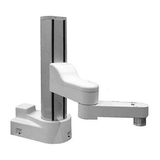
The PreciseFlex 1300 Robot (Figure 2-2) is a 3-axis SCARA robot composed of a J1-Axis with a rotation of +/-176°, a Z-axis with a stroke ranging from a standard travel of 300 mm to a maximum of Copyright © 2023 Brooks Automation, Inc. -
Page 19: Guidance 2400 Controller
The PreciseFlex 1400 is a 4-axis version of this robot. It is configured at the factory by adding a Theta rotational axis to the PreciseFlex 1300 and a 4th motor driver to the robot’s embedded controller. The PreciseFlex 1400 is visually nearly identical to the 1300 except that the tool mounting flange extends 10 mm lower. - Page 20 Controls Bay and are pictured in the System Diagram and Coordinate Systems section. For detailed information on the controller including interfacing information, please see the Guidance 3000/2000 Controllers, Hardware Introduction and Reference Manual. Copyright © 2023 Brooks Automation, Inc.
-
Page 21: Low-Voltage Power Supply
The Guidance 2400 requires 0.7 amps of 24VDC power for its logic circuits and 2 amps for IO power, for a total of 2.7 amps. For applications using remote IO or Ethernet cameras, Brooks recommends a total of 4 amps. This power is obtained from a 24VDC power supply included with the robot. -
Page 22: Remote Front Panel, E-Stop Box, And Manual Control Pendant
Remote Front Panel connector mounted on the robot's Facilities Panel, which is located on the back of the J1 housing. Each of these units provides the hardware signals to permit power to be enabled and disabled. Copyright © 2023 Brooks Automation, Inc. -
Page 23: Remote Io Module
RS-232 serial line. An enhanced version of the RIO adds 4 analog input signals, a second RS-232 port and one RS-422/485 serial port. In addition, expansion boards will soon be offered that cost effectively add additional isolated digital inputs and outputs in groups of 32 each to the basic RIO. Copyright © 2023 Brooks Automation, Inc. -
Page 24: Machine Vision Software And Cameras
To simplify this approach, in the future, Precise will offer an optional Arm Mounted Camera Kit. This kit will permit a IDS Imaging Ethernet Camera to be easily attached to the PreciseFlex robot's outer link in a number of different positions. Copyright © 2023 Brooks Automation, Inc. -
Page 25: Controller Status Led
The processor may be executing the firmware debugger, dBug. Normal Blinks 1 time operation, The controller is executing in its standard operating mode and motor power is per second motor power disabled. Copyright © 2023 Brooks Automation, Inc. -
Page 26: Machine Safety
2000 volts by means of MOVs at the line input. Transient over voltage (< 50 µs) may not exceed 2000 V phase to ground, as per EN61800-31996. It is protected against over current by two 6.3 amp, 250V fuses, Wickman PN 1941630000. Copyright © 2023 Brooks Automation, Inc. -
Page 27: Robot Controls Bay
The 24VDC power supply is also an open frame supply with high voltage terminals and heat sink surfaces exposed when the Controls Bay is exposed. Do not operate the robot if the Controls Bay is not completely inserted in the J1 Base Housing. Copyright © 2023 Brooks Automation, Inc. -
Page 28: Releasing A Trapped Operator: Brake Release Switch
If a mechanical limit stop is changed, it is important that the software “Soft stop limit” and "Hard stop limit" settings be adjusted to be inside of the new mechanical restrictions. The software limit stop Copyright © 2023 Brooks Automation, Inc. -
Page 29: E-Stop Stopping Time And Distance
These 3D safety zones can be used to: a. Approximately model the volume of stationary objects or personnel working areas to prevent the robot from inadvertently entering this volume and causing a collision (“keep out zones”). Copyright © 2023 Brooks Automation, Inc. - Page 30 The supported zone shapes are rectangular volumes, cylinders and spheres. To define a safety zone, the type of safety zone must be specified along with its origin and dimensions. Figure 2-6: Rectangular Volume Figure 2-7: Cylinder Copyright © 2023 Brooks Automation, Inc.
- Page 31 NOTE: Safety zone testing is based on the TCP of the robot. Therefore, it is very important that the position of the tool center point relative to the robot’s tool mounting flange is set correctly. Please see the Robot.Tool property for information on defining the TCP. Copyright © 2023 Brooks Automation, Inc.
- Page 32 Cylinder, keep out zone Sphere, keep out zone Rectangular volume, stay within zone Cylinder, stay within zone Sphere, stay within zone Non-rotated rectangular volume, Z downward speed restrict zone Non-rotated rectangular volume, XY speed restrict zone Copyright © 2023 Brooks Automation, Inc.
- Page 33 Z/XY spd mm/sec it should be a negative value and defaults to -200. The second value is the maximum permitted speed in the horizontal XY plane (when within the safety zone), and defaults to 200 mm/sec. Copyright © 2023 Brooks Automation, Inc.
-
Page 34: Safety Standards Reference Material
While the PreciseFlex is a light-duty robot that can only apply approximately 120 Newton's of force, it is very important for operators to keep their hands, arms and especially their head out of the robot’s operating volume. Copyright © 2023 Brooks Automation, Inc. - Page 35 E-stop circuitry. Please refer to the ANSI/RIA R15.06 Safety Standard for Industrial Robots or EN ISO 10218-2-2007, Robots for Industrial Environments, Safety Requirements, for information on recommended safe operating practices and enclosure design for robots of various sizes and payloads. Copyright © 2023 Brooks Automation, Inc.
-
Page 36: Installation Information
The Facilities Panel on the back of the J1-Axis housing includes the following: System AC input power receptacle Lighted AC on/off power switch Two 4 mm OD pneumatic tubing fittings (one-touch type tube insertion) Connectors for controller input and output signals Controls Bay fan filter Copyright © 2023 Brooks Automation, Inc. -
Page 37: System Dimensions
Part Number: PF10-DI-00010 Rev. A System Dimensions System Dimensions Both top and left views for the PreciseFlex 1300/1400 are shown below. All dimensions are in millimeters. PreciseFlex 1300 and 1400 Top View PreciseFlex 1300 Left Side View Copyright © 2023 Brooks Automation, Inc. -
Page 38: Mounting Instructions
200 Newton's without moving or vibrating. The robot base has an integrated recessed bolting pattern that accommodates three M6 SHCS mounting screws located as illustrated below. Copyright © 2023 Brooks Automation, Inc. -
Page 39: Tool Mounting - Preciseflex 1300/1400
Tool Mounting - PreciseFlex Part Number: PF10-DI-00010 Rev. A 1300/1400 Tool Mounting - PreciseFlex 1300/1400 The PreciseFlex Outer Link has been designed to permit tooling to be easily attached and interfaced. To facilitate electrical interfacing, digital I/O, camera and light power, and Ethernet signals are available on a "ZIO PCB"... -
Page 40: Accessing The Controller And Power Supplies
Both the PreciseFlex 1300 and 1400 provide the same ISO standard mounting flange for attaching tooling and end-effectors. Shown below are the details of the tool mounting flange that conforms to ISO 9409-1. -
Page 41: Power Requirements
Remote Front Panel connector. Alternately, you can also purchase a Precise Manual Control Pendant. The Pendant has an integrated E-Stop button and provides a convenient means for manually jogging the robot via a portable hand-held device. Copyright © 2023 Brooks Automation, Inc. -
Page 42: Hardware Reference
50-60 Hz. The AC power to the robot is controlled by a green backlit On/Off Switch. To simplify interfacing, most of the electrical interfaces provided by the robot's embedded Guidance Controller are available on the Facilities Panel. These include: Copyright © 2023 Brooks Automation, Inc. -
Page 43: Digital Input Signals
The Facilities Panel includes 12 general purpose optically isolated digital input signals (in addition to those signals that are available at the ZIO Board in the outer link). These lines are accessed in a single DB15 connector. Copyright © 2023 Brooks Automation, Inc. - Page 44 24 VDC to signal a logical low value. This configuration is compatible with "sinking" (NPN) sensors. Copyright © 2023 Brooks Automation, Inc.
- Page 45 10010 Digital Input 10 10012 Digital Input 12 10001 Digital Input 1 10003 Digital Input 3 10005 Digital Input 5 10007 Digital Input 7 10009 Digital Input 9 10011 Digital Input 11 24 VDC Copyright © 2023 Brooks Automation, Inc.
-
Page 46: Digital Output Signals
Alternately, the output signals can be configured as "sourcing," i.e. the external equipment must pull-down an output pin to ground and the controller pulls this pin to 24 VDC when the signal is asserted as true. This configuration is compatible with "sinking" (NPN) devices. Copyright © 2023 Brooks Automation, Inc. - Page 47 Always disconnect the main AC power before accessing the Controls Bay. The pin out for the Digital Output Connector and the corresponding GPL signal numbers are described in the following table. Copyright © 2023 Brooks Automation, Inc.
-
Page 48: Ethernet Interface
Precise robots are equipped with communication interface boards (MCIMs or MIDS3s) that include an Ethernet switch that implements two 10/100 Mbit Ethernet ports. This capability was designed to permit the controller to be interfaced to multiple Ethernet devices such as other Precise controllers Copyright © 2023 Brooks Automation, Inc. -
Page 49: Remote Front Panel / Mcp / E-Stop Interface
"on" button with a high power "on" indicator lamp, and a RS- 232 interface for a Manual Control Pendant (MCP). These signals are provided in a DB25 female connector mounted on the robot's Facilities Panel. Copyright © 2023 Brooks Automation, Inc. - Page 50 The Auto/Manual signal is daisy chained to all controllers in the servo network. Auto/Manual 1 (If no front panel or Auto mode, connect to pin 15). Redundant Auto/Manual input signal. Copyright © 2023 Brooks Automation, Inc.
- Page 51 The System Software also uses this as a means for asserting a hardware E-Stop condition during normal operation. This signal is normally held high. Force ESTOP_L. Redundant Force ESTOP_L output signal. Force ESTOP_L. Redundant Force ESTOP_L output signal. Copyright © 2023 Brooks Automation, Inc.
-
Page 52: Rs-232 Serial Interface
PC "COM" ports. A straight through DB9 to DB9 cable can be used to connect the Guidance System to a PC. The following table defines the pin assignments for this connector. Description Not used Copyright © 2023 Brooks Automation, Inc. -
Page 53: Outer Link And Zio Pcb
RS485 serial line that allows the controller to scan the ZIO I/O with a nominal period of 4 milliseconds. The DIO signals and the optional arm mounted camera and ring light power lines are accessible via a DB25 female connector that is mounted on the bottom of the Outer Link. Copyright © 2023 Brooks Automation, Inc. - Page 54 GPL and the part information for the required hardware plug. If the robot is equipped with the optional solenoid valves that control two internal air lines, two of the digital output signals are internally pre-wired as indicated below. Copyright © 2023 Brooks Automation, Inc.
- Page 55 Web Operator Interface. Digital Output 4 Digital Output 6 Digital Output 8 Ground 24 VDC 24 VDC 10034 Digital Input 2 10036 Digital Input 4 10038 Digital Input 6 10040 Digital Input 8 Ground Copyright © 2023 Brooks Automation, Inc.
- Page 56 Green - Blinks fast (about 10Hz) when the ZIO is not communicating with the robot's controller. Blinks slowly (about 1Hz) during normal communication. LED1 (Activity / Error) Red - Off at initial power-up and during normal communications. On if communications is lost after being established. Copyright © 2023 Brooks Automation, Inc.
- Page 57 Blinks 8 times Processor overheating, motor power off. You have 5 minutes to save any programs or data. per second After 5 minutes, the processor will shut down and needs to be rebooted. Copyright © 2023 Brooks Automation, Inc.
-
Page 58: Software Reference
Signal Number Label Description Optional solenoid 1 Z I/O board output 1 Optional solenoid 2 Z I/O board output 2 Z I/O board output 3 Z I/O board output 4 Z I/O board output 5 Copyright © 2023 Brooks Automation, Inc. -
Page 59: Zio Dedicated Digital Outputs
Outer Link status light. Set to 1 to turn on the light. Normally parameter 8040 “Power State DOUT” (DataID 235) is set to this signal number so that the Outer Link light displays the robot controller's execution state. Copyright © 2023 Brooks Automation, Inc. -
Page 60: Service Procedures
The zero positions must be reestablished if a motor is replaced, if a motor's encoder cable to the controller is disconnected, or if the encoder backup battery located at the controller is replaced. Copyright © 2023 Brooks Automation, Inc. - Page 61 Load Cal_PP into the controller's memory using either the Guidance Development Environment (GDE) or the web Operator Control Panel. Manually raise the Z-axis so that it is firmly pressed against its upper hard stop limit. Copyright © 2023 Brooks Automation, Inc.
- Page 62 If your robot is equipped with a Theta axis, insert one of the supplied M3x40 mm dowel pins into the hole on the Theta flange. Rotate the flange until the pin registers with a slot in the outer link. This should center the flange within its range of travel. Copyright © 2023 Brooks Automation, Inc.
-
Page 63: General Belt Tensioning
Production_a versions of the robot and later. Tension Values and Constants Belt Mass (g/m) Width (mm) Span (mm) Tension (N) J1 Stage 1 J1 Stage 2 Z Stage 1 Z Stage 2 J3 Stage 1 Copyright © 2023 Brooks Automation, Inc. -
Page 64: J1-Axis Drive Procedures
Disconnect the main AC power to the robot. Detach the robot from its mounting surface. The robot should be gently placed on its side on a protective layer to avoid scratching or damaging the robot's surface. Copyright © 2023 Brooks Automation, Inc. - Page 65 AC power to the robot. To remove the 1st Stage Belt, remove the M3x8 mm Locking Screw. Then loosen the M4x45 mm Spring Tension Screw to eliminate the tension on the 1st Stage Belt. Copyright © 2023 Brooks Automation, Inc.
-
Page 66: Replacing And Tensioning The J1-Axis Belts
In addition, the motor power supply provides 320 VDC volts and takes about two minutes to bleed down after power is disconnected. Disconnect the AC power to the robot before accessing the Controls Bay. Copyright © 2023 Brooks Automation, Inc. - Page 67 This will permit the top cover for the J1-axis to be lifted after it is unscrewed. The 2nd Stage Belt is located below the top cover of the J1-axis. The following picture illustrates the 2nd Stage Idler and Tensioner Assembly after the J1-axis top cover is raised. Copyright © 2023 Brooks Automation, Inc.
- Page 68 Adjust the Acorn Nut to push the Idler Roller against the belt. Measure the belt tension using the Gates Sonic Tension Meter on the non-idler side of the belt. Compare the tension to that specified in the Belt Tensioning Table. Copyright © 2023 Brooks Automation, Inc.
-
Page 69: Z-Axis Drive Procedures
Do not touch unshielded pins and conductors unless the main AC power to the robot is first disconnected. To replace this assembly, perform the following operations: Step Action Lower the Z-axis to the bottom of its travel. Disconnect the main AC power to the robot. Copyright © 2023 Brooks Automation, Inc. - Page 70 To relieve the tension on the 1st Stage Belt, first use a 8 mm open-ended wrench to loosen (but don't remove) the four nylon Z-Motor Assembly Retaining Nuts on the back of the Z-axis. Copyright © 2023 Brooks Automation, Inc.
-
Page 71: Replacing And Tensioning The Z-Axis Belts
PreciseFlex robot are operated at between 160 VDC and 320 VDC. As such, the motor wires present a high-risk. Do not touch unshielded pins and conductors unless the main AC power to the robot is first disconnected. Copyright © 2023 Brooks Automation, Inc. - Page 72 To replace the belt, you must have available a Gates TruMotion Belt (Precise P/N PF10-MC- X0077). Then perform the following operations: Step Action Move the Inner Link to approximately the middle of travel of the Z-Axis to permit access to the lower section of the 2nd Stage Belt. Copyright © 2023 Brooks Automation, Inc.
- Page 73 The belt is a continuous loop and is attached to the Inner Link Carriage by a Belt Clamp with four M3 SHCS. Loosen all four screws and remove two on either side in order slip out the belt. Slip out the old belt and slide the new belt into the clamp. Copyright © 2023 Brooks Automation, Inc.
-
Page 74: J3-Axis And Theta Drive Procedures
Since these drives are similar, they are both discussed in this section. These motor assemblies can be replaced while the robot is mounted in the standard vertical orientation. To replace either assembly, perform the following operations: Copyright © 2023 Brooks Automation, Inc. - Page 75 Back off the Jam Nut on the Tensioning Bolt. Back off the Tensioning Bolt to eliminate the 1st Stage Belt tension. Remove the belt by sliding if off of the large pulley and then the motor pulley. Copyright © 2023 Brooks Automation, Inc.
-
Page 76: Replacing And Tensioning The J3-Axis Belts
Follow the instructions in the previous section to remove the Inner Link Cover and the Inner Link Cable Cover. Loosen (but do not remove) the J3-Axis Motor Bracket Screws and back off its Jam Nut and Tensioning Bolt. Copyright © 2023 Brooks Automation, Inc. - Page 77 Replacing the J3-Axis or Theta Motor Assembly). This can be done by removing the M4 Locking Screw, backing off the Jam Nut and Bolt, and removing the M4 Shoulder screw that retains the pivoting assembly. Copyright © 2023 Brooks Automation, Inc.
- Page 78 Remove the J3-Axis 2nd Stage Belt by slipping it over 1st Stage pulley. Install the new belt by sliding it over the lower flanged pulley and around the posts as shown below. Copyright © 2023 Brooks Automation, Inc.
-
Page 79: Replacing And Tensioning The Theta Belts
The 1st Stage Belt for the Theta-Axis is located in the Inner Link. To replace or tension this belt, it must be accessed using the same procedures as those described in the section on Replacing the Copyright © 2023 Brooks Automation, Inc. - Page 80 As required, adjust the motor position and belt tension by turning the Tensioning Bolt. Tighten the three Motor Bracket Screws and verify that the belt tension is still correct. Tighten the Jam Nut to hold the Tensioning Bolt in place. Copyright © 2023 Brooks Automation, Inc.
- Page 81 Unplug all connections to the ZIO board contained in the Outer Link and remove this board. The Outer Link should look as follows. Loosen the M4 Tension Idler Locking Screw to permit the Idler to move. Copyright © 2023 Brooks Automation, Inc.
-
Page 82: Replacing Control Electronics Components
J1-Axis housing. To access the Controls Bay, remove the screws that attach the Facilities Panel to the back of the J1-Axis housing and then slide out the bay. Copyright © 2023 Brooks Automation, Inc. - Page 83 Then unscrew the four M4x10 SHCS that hold the supply in place. During installation of the replacement supply, Loctite 222 should be applied to the screw threads. All cabling should be installed and tied down to the appropriate cable tie mounts. Copyright © 2023 Brooks Automation, Inc.
- Page 84 The replacement fan should be reconnected to the same plug and the wires should be routine in a manner similar to the original fan. The fan is mounted to the Facilities Panel using four M4x25 FHCS and nylon nuts Copyright © 2023 Brooks Automation, Inc.
-
Page 85: Appendices
Maximum Z down force - 200N PreciseFlex 1300: 5 kg Payload PreciseFlex 1400: 4 kg Controller AVAILABLE GUIDANCE CONTROLLERS: Guidance 2410C (G2XD-EA-C2410 Embedded Standard), Guidance 2410B (G2XD-EA-B2410), Guidance 2414B (G2XD-EA-B2414), Controller Guidance 2416B (G2XD-EA-B2416) Copyright © 2023 Brooks Automation, Inc. - Page 86 Three methods available: DIO MotionBlocks (PLC), embedded Guidance Programming Interface Language (standalone), PC controlled over Ethernet using TCP/IP. General Required Power Input range: 90 to 264 VAC single phase, 50-60 Hz, 500-watts maximum. Weight 34 kg typical, will vary with size Copyright © 2023 Brooks Automation, Inc.
-
Page 87: Preciseflextm 1300/1400 Environmental Specifications
Range & Features Ambient temperature 5ºC to 40ºC Ingress protection IP51. Protected against light dust and water drips. Storage and shipment temperature -25ºC to +55ºC Humidity range 5 to 90%, non-condensing Altitude Up to 3000m Copyright © 2023 Brooks Automation, Inc. -
Page 88: Appendix B: Frequently Asked Questions
500 VA and plugging the isolation transformer into the GFI circuit. Isolation transformers of this type are readily available and cost approximately $100-$150.For example, the following transformer, a Hammond 171E is available from www.mouser.com as part number 546-171E for $130. ROBOT SOFTWARE None Copyright © 2023 Brooks Automation, Inc. -
Page 89: Appendix C: Spare Parts Lists
PF10-MC-X0086 Z-Axis Stage 2 Belt PF10-MC-X0077 J3 Motor Assembly PF10-MA-00050 J3 Stage 1 Belt PF10-MC-X0106 J3 Stage 2 Belt PF10-MC-X0079 J4 Motor Assembly PF10-MA-00051 J4 Stage 1 Belt PF10-MC-X0080 J4 Stage 2 Belt PF10-MC-X0080 Copyright © 2023 Brooks Automation, Inc. -
Page 90: Appendix D: System Schematics
Appendices PreciseFlex 1300/1400 Robot Appendix D: System Schematics Part Number: ###### Rev. A Appendix D: System Schematics Copyright © 2022, Brooks Automation, Inc. - Page 91 Brooks Automation Appendices Part Number: ###### Rev. A Appendix D: System Schematics Copyright © 2022, Brooks Automation, Inc.
- Page 92 Appendices PreciseFlex 1300/1400 Robot Appendix D: System Schematics Part Number: ###### Rev. A Copyright © 2022, Brooks Automation, Inc.
Need help?
Do you have a question about the PreciseFlex 1300 and is the answer not in the manual?
Questions and answers