Table of Contents
Advertisement
Quick Links
Advertisement
Table of Contents

Subscribe to Our Youtube Channel
Related Manuals for Brooks PreciseFlex 400


Summary of Contents for Brooks PreciseFlex 400
- Page 1 PreciseFlex 400 Robots User Manual Part Number PF40-DI-00010, Revision A...
- Page 2 © 2023 Brooks Automation. All rights reserved. The information included in this manual is proprietary information of Brooks Automation, and is provided for the use of Brooks customers only and cannot be used for distribution, reproduction, or sale without the express written permission of Brooks Automation.
- Page 3 +1-408-224-2838 (PreciseFlex Europe support_preciseflex@brooksautomation.com +81 120-255-390 (Toll Free) Japan +81 45-330-9005 (Local) http://www.brooks.com/ China +86 21-5131-7066 +886 080-003-5556 (Toll Free) Taiwan +886 3-5525258 (Local) Korea 1800-5116 (Toll Free) +65 1-800-4-276657 (Toll Free) Singapore +65 6309 0701 (Local) Copyright © 2023, Brooks Automation...
- Page 4 Fax: +82-31-287-2111 Nisso Bldg. No 16, 9F Carretera Huinalá km 2.8 3-8-8 ShinYokohama, Kohoku-ku Parque Industrial Las Américas Brooks Technology (Shanghai) Brooks Automation (S) Pte Ltd Yokohama, Kanagawa 222-0033 66640 Apodaca, NL Mexico Limited 51-18-C1 Menara BHL, Tel: +81-45-477-5570 Tel: +52 81 8863-6363 2nd Floor, No.
- Page 5 Brooks Automation Part Number: PF40-DI-00010 Rev. A Revision History Revision Date Action Author Released manual at Rev. A 08/04/2023 to follow standard Brooks M. Ashenfelder technical publication styles.” Copyright © 2023, Brooks Automation...
-
Page 6: Table Of Contents
Voltage and Power Considerations Mechanical and Software Limit Stops Stopping Time and Distance Releasing a Trapped Operator: Brake Release Switch 3. Collaborative Robot Safety General Information Summary Background Determining a Machine’s Required Performance Level (PLr). Copyright © 2023, Brooks Automation... - Page 7 Controlling the PreciseFlex Servo Grippers Overview Software Revision Controlling the Gripper Gripper Squeeze (Simple Method) Gripper Squeeze (Asymmetric Method) End of Travel Sensor Grip Test and Squeeze Check Servo Gripper Controller Digital Inputs and Outputs Copyright © 2023, Brooks Automation...
- Page 8 Appendix E: Belt Tensions, Gates Tension Meter Appendix F: Example Performance Level Evaluation Example Workcell Description Normal Operator Interaction with Robot Possible Low Frequency (rare) Interaction with Robot Appendix G: TUV Verification of PF400 Collision Forces Copyright © 2023, Brooks Automation...
- Page 9 Brooks Automation Part Number: PF40-DI-00010 Rev. A Appendix H: Table A2 from ISO/TS 15066: 2016, Biomechanical Limits Appendix I: Safety Circuits for PF400 500gm Payload Appendix J: Robot Anatomy Copyright © 2023, Brooks Automation...
-
Page 10: Safety
1. Safety Safety Setup Brooks uses caution, warning, and danger labels to convey critical information required for the safe and proper operation of the hardware and software. Read and comply with all labels to prevent personal injury and damage to the equipment. -
Page 11: Explanation Of Hazards And Alerts
Notice indicates a situation or unsafe practice which, if not avoided, may result in equipment damage. The Notice signal word is white on blue background with no icon. Copyright © 2023, Brooks Automation... -
Page 12: Alert Example
Part Number: PF40-DI-00010 Rev. A Alert Example The following is an example of a Warning hazard alert. Number Description How to Avoid the Hazard Source of Hazard and Severity General Alert Icon Signal Word Type of Hazard Hazard Symbol(s) Copyright © 2023, Brooks Automation... -
Page 13: General Safety Considerations
Using parts with different inertial properties with the same robot application can cause the robot’s performance to decrease and potentially cause unplanned robot motion that could result in serious personal injury. Do not use unauthorized parts. Confirm that the correct robot application is being used. Copyright © 2023, Brooks Automation... - Page 14 Use of this product in a manner or for purposes other than for what it is intended may cause equipment damage or personal injury. Only use the product for its intended application. Do not modify this product beyond its original design. Always operate this product with the covers in place. Copyright © 2023, Brooks Automation...
-
Page 15: Mechanical Hazards
Do not operate the product without its protective covers in place. While the collaborative robotics system is designed to be safe around personnel, gravity and other factors may present hazards and should be considered. Copyright © 2023, Brooks Automation... -
Page 16: Electrical Hazards
Improper electrical connection or connection to an improper electrical supply can result in electrical burns resulting in equipment damage, serious injury, or death. Always provide the robot with the proper power supply connectors and ground that are compliant with appropriate electrical codes. Copyright © 2023, Brooks Automation... -
Page 17: Ergonomic Hazards
This product has a high center of gravity which may cause the product to tip over and cause serious injury. Always properly restrain the product when moving it. Never operate the robot unless it is rigidly mounted. Copyright © 2023, Brooks Automation... - Page 18 Part Number: PF40-DI-00010 Rev. A Trip Hazard Cables for power and communication and facilities create trip hazards which may cause serious injury. Always route the cables where they are not in the way of traffic. Copyright © 2023, Brooks Automation...
-
Page 19: Emergency Stop Circuit (E-Stop)
Do not override or bypass the emergency stop circuit. Recycling and Hazardous Materials Brooks Automation complies with the EU Directive 2002/96/EU Waste Electrical and Electronic Equipment (WEEE). The end user must responsibly dispose of the product and its components when disposal is required. -
Page 20: Introduction To The Hardware
Appendix J: Robot Anatomy for detailed illustrations. The PreciseFlex 400 Robot is a 4-axis robot that includes an embedded Guidance 1400B 4-axis motion controller, a 48 VDC motor power supply, and a 24 VDC logic power supply located inside the base of the robot. In addition, it may optionally include an electric gripper and electric gripper controller. -
Page 21: Release History
J2 timing belt are installed. In January 2017, a longer life Ethernet cable is expected to be released which should last for the life of the robot running continuous duty for at least three years. Copyright © 2023, Brooks Automation... -
Page 22: System Diagram And Coordinate Systems
When inner link is closest to the bottom, the Z-axis is at its 0 position in the Joint Coordinate system and Z=30 mm in the World Coordinate system. As the robot arm moves upwards, both its joint position and the World Z Coordinate increase in value. Copyright © 2023, Brooks Automation... - Page 23 It is not necessary for the control system to be operating for the brake release to function; the only requirement is providing 24 VDC to the controller. Care should be taken to support the Z-axis when the brake release button is pushed, as the axis will fall due to gravity. Copyright © 2023, Brooks Automation...
-
Page 24: System Components
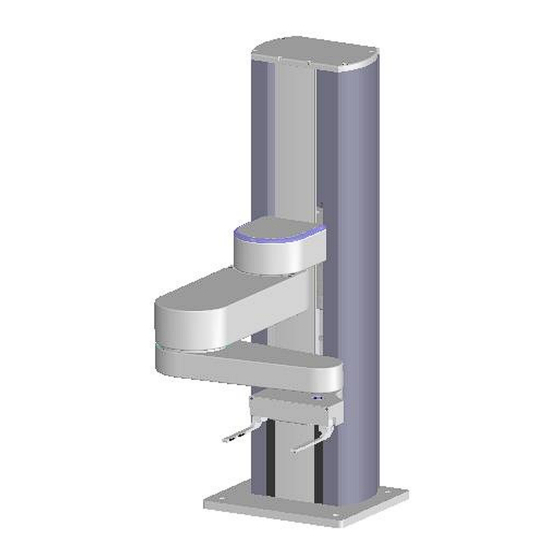
System Components PreciseFlex 400 Robot NOTE: See Appendix J: Robot Anatomy for detailed illustrations. The PreciseFlex 400 Robot (pictured in Figure 2-2 and defined in Table 2-2) is a 4-axis robot that may optionally include an electric or pneumatic gripper. -
Page 25: Optional Linear Axis Module
The robot may also be rotated 90 degrees so that it faces the connector end cap of the Linear Axis. In this case the Linear Axis extends the robot’s X-axis travel, if the appropriate SW parameter is changed. See Software Reference for more information. Copyright © 2023, Brooks Automation... -
Page 26: Mounting Of Robot And Linear Axis Module
The controller includes local digital IO. It also supports RS-232 and RS- 485 serial communication and an optional PreciseFlexRemote IO module. It contains two Ethernet ports. The controller and power supplies are shown in the system diagram in Figure 2-4. Copyright © 2023, Brooks Automation... -
Page 27: Low-Voltage Power Supplies
1000A/B Controllers Manual (G1X0-DI-A0010). Low-Voltage Power Supplies The PreciseFlex 400 Robot has an integrated 125-Watt, 24 VDC Power Supply that accepts a range of AC input from 90 V to 264 V and an integrated 400 W, 48 VDC Power Supply for the motors. -
Page 28: Energy Dump Circuit
In order to avoid bus pump up, an Energy Dump Circuit is connected to the 48 VDC bus. See Figure 2-5. Figure 2-5: 48 VDC Supply Copyright © 2023, Brooks Automation... -
Page 29: Remote Front Panel, E-Stop Box, And Manual Control Pendant
For users who want to have IO available at the base of the robot, an optional IO module (Figure 2-8) may be added. This module provides 12 digital inputs and 8 digital outputs in a 25-pin Dsub connector at the robot connector panel and is connected via RS-485 to the robot controller. Copyright © 2023, Brooks Automation... -
Page 30: Remote Io Module (Ethernet Version)
Figure 2-9. Electrical Shock The RIO contains unshielded 24 VDC signals and pins. This product is intended to be mounted in a cabinet or machine chassis that is not accessible when power is turned on. Copyright © 2023, Brooks Automation... -
Page 31: Machine Vision Software And Cameras
Read ENISO 10218-1:2011 and 10218-2:2011 Robots for Industrial Environments, Safety Requirements, ISO/TS 15066 Robots and Robotic Devices – Collaborative Robots, and ISO 13849- 1:2006 Safety of machinery — Safety-related parts of control systems. Copyright © 2023, Brooks Automation... -
Page 32: Standards Compliance And Agency Certifications
Manual Control Mode to a maximum of 250 mm per second for safety. While the PreciseFlex 400 is a light-duty robot that can only apply approximately 20-60 Newtons of force, it is very important for operators to keep their hands, arms and especially their head out of the robot’s operating volume. -
Page 33: Voltage And Power Considerations
AC line power is turned on. The PreciseFlex 400 power supplies have an input range of 100 to 240 VAC, +/- 10%, 50/60 Hz. Inrush current can be as high as 100 Amps at 240 VAC for short periods of time. The power supplies are protected against voltage surge to 2000 Volts. -
Page 34: Releasing A Trapped Operator: Brake Release Switch
267 to the desired delay. If this delay is set to 0, the high-power relay will be disabled within 1ms. For the PreciseFlex 400 robot, the shoulder, elbow, and wrist axes do not have mechanical brakes. Therefore, leaving the motor power enabled for 0.5 sec allows the servos to decelerate the robot. -
Page 35: Collaborative Robot Safety
Collaborative Robots. “Collaborative Operation” is defined in section 3.4 of 10218:1:2011 as “a state in which purposely designed robots work in direct cooperation with a human within a defined workspace”. One of the requirements listed as sufficient to meet the 10218:1:2011 standard is: Copyright © 2023, Brooks Automation... -
Page 36: Determining A Machine's Required Performance Level (Plr)
PL for a PF400 workcell is given in Appendix F: Example Performance Level Evaluation, where it is shown that a PL of “a” is sufficient for the workcell. Figure 3-1: Flow chart for Determining Performance Levels, Risk Estimation by Risk Graph Copyright © 2023, Brooks Automation... -
Page 37: Maximum Allowable Forces To Prevent Operator Injury
Additional research for safety for collaborative robots is ongoing. The Institute for Occupational Safety and Health (IFA) in Germany has surveyed the literature relating to crushing and impact injuries. Figure 3-2 summarizes their findings, which has contributed to the current draft 15066 Copyright © 2023, Brooks Automation... -
Page 38: Types Of Forces
1. Clamping/squeezing force. This is the quasi-static case of the robot pressing a compliant part of the human body against a surface. This force should be considered when the robot is under manual control and for low speed collisions. Copyright © 2023, Brooks Automation... -
Page 39: Robot Testing And Safety Circuits
Based on Table A2 from ISO/TS 15066, Brooks has selected the maximum impact force (transient force) in free space to be 280 N for the hand and forearm and 130 N for the skull for a collaborative robot. -
Page 40: Controller Requirements
Notwithstanding the above, PreciseFlex controllers are designed so that no single failure can disable the safety features in the controller and cause an uncontrolled motion. However, the 500 gm payload PF400 robots are not Category 3 robots as they cannot cause serious injury and the Copyright © 2023, Brooks Automation... - Page 41 A further reduction in force is set by collaborative force limits in software, so that the clamping/squeezing force (quasi-static) does not exceed 60 N. See Table 3-1. Table 3-1: PreciseFlex 400 Maximum Forces, Newtons PreciseFlex 500 gm Unlimited Current Limited...
- Page 42 4 ms by the software running in the CPU or the motor power is disabled and the brakes are set. This circuit is both PLd and CAT 3 compliant. This Copyright © 2023, Brooks Automation...
-
Page 43: Test Procedure For The Pf400
In this test setup a digital force gauge (traceable to NIST standards) is mounted below (or to the left for horizontal testing) of the gripper of the robot and a “hand compliance simulator” consisting of two plates separated by compression springs with a compression constant of 75 N/mm equal to the Copyright © 2023, Brooks Automation... -
Page 44: Robot Workcell Design
Work cell Design Recommendations for the PF400 Work cell designers are referred to EN ISO 10218-2:2011 for information on designing safe work cells. Copyright © 2023, Brooks Automation... - Page 45 When the robot is moving horizontally in and out of the storage racks the maximum forces are well below any injury threshold. Appendix F: Example Performance Level Evaluation for an example PLr evaluation for an example PF400 workcell. Copyright © 2023, Brooks Automation...
-
Page 46: Installation Information
The Facilities Panel (Figure 4-1 Table 4-1) at the base of the robot (and optional linear axis end cap) includes: System AC input power receptacle Lighted AC on/off power switch Connectors for controller input and output signals Copyright © 2023, Brooks Automation... -
Page 47: System Dimensions
E-Stop and Cell Interlock Signals Power Entry Module For IEC plug. Contains dual fuse drawer. Power Status Light Blinks to indicate power status System Dimensions Figure 4-2 shows top and right views. All dimensions are in millimeters. Copyright © 2023, Brooks Automation... - Page 48 The Mounting Dimensions for PF400, Standard Reach, are shown in Figure 4-3 through Figure 4-7. For XR robot, R575 increases to R731, and inner link length increases from 225 to 302 mm. Figure 4-3: Working Volume Copyright © 2023, Brooks Automation...
- Page 49 Brooks Automation 4. Installation Information Part Number: PF40-DI-00010 Rev. A System Dimensions Figure 4-4: Finger Mount Height from Base PF400 Copyright © 2023, Brooks Automation...
- Page 50 4. Installation Information (Undefined variable: MyVariables.ProductName) System Dimensions Part Number: PF40-DI-00010 Rev. A Figure 4-5: PreciseFlex E-Gripper, Interface Drawing PF400 Copyright © 2023, Brooks Automation...
- Page 51 Brooks Automation 4. Installation Information Part Number: PF40-DI-00010 Rev. A System Dimensions Figure 4-6: ISO Flange, Installation PF400 Copyright © 2023, Brooks Automation...
- Page 52 4. Installation Information (Undefined variable: MyVariables.ProductName) System Dimensions Part Number: PF40-DI-00010 Rev. A Figure 4-7: Dual Gripper, PF400 2.5 kg, Standard Reach Copyright © 2023, Brooks Automation...
-
Page 53: Linear Axis Mounting Dimensions
When replacing the top cover, be sure the tape seals are inside the slot in the top cover and not crushed. Figure 4-8: Linear Axis Mounting Dimensions Figure 4-9: Linear Axis Mounting Dimensions Copyright © 2023, Brooks Automation... -
Page 54: Unpacking And Handling Instructions
(4) M6 SHCS mounting screws located as shown above. Tool Mounting The PreciseFlex 400 is typically supplied with an electric gripper. In some cases, a pneumatic gripper may be supplied by PreciseFlex or by the end user. However, the standard robot does not include pneumatic lines, so if pneumatic tooling is needed, the robot must be ordered with pneumatic lines installed. -
Page 55: Accessing The Robot Controller
Both manuals are available in PDF format and are also contained in the PreciseFlex Library. Power Requirements The PreciseFlex 400 power supplies have an input range of 100 to 240 VAC, +/- 10%, 50/60 Hz. The robots are equipped with an IEC electrical socket that accepts country specific electrical cords. -
Page 56: Hardware Reference
The rest of the digital inputs and outputs are daisy chained to a second connector on the MIDS board for use if needed. Some of these signals are used when the pneumatic gripper option is installed. Copyright © 2023, Brooks Automation... - Page 57 This button provides a ground return from the Z column brake to ground bypassing the transistor that performs this function under computer power so that the brake can be released manually without motor power being enabled. Figure 5-1 through Figure 5-19 show the schematics. Copyright © 2023, Brooks Automation...
- Page 58 5. Hardware Reference (Undefined variable: MyVariables.ProductName) System Schematics Part Number: PF40-DI-00010 Rev. A Figure 5-1: System Overview, PF400 with Linear Axis Copyright © 2023, Brooks Automation...
- Page 59 Brooks Automation 5. Hardware Reference Part Number: PF40-DI-00010 Rev. A System Schematics Figure 5-2: FFC Boards Revision B, PF400, SCH, FFC Interface & VLS Boards Copyright © 2023, Brooks Automation...
- Page 60 5. Hardware Reference (Undefined variable: MyVariables.ProductName) System Schematics Part Number: PF40-DI-00010 Rev. A Figure 5-3: SCH, FFC Interface, VLS & DIO Boards Copyright © 2023, Brooks Automation...
- Page 61 Brooks Automation 5. Hardware Reference Part Number: PF40-DI-00010 Rev. A System Schematics Figure 5-4: FFC Boards Revision C PF400, SCH, FLC Interface, VLS & DIO Boards Copyright © 2023, Brooks Automation...
- Page 62 5. Hardware Reference (Undefined variable: MyVariables.ProductName) System Schematics Part Number: PF40-DI-00010 Rev. A Figure 5-5: SCH, FFC Interface, VLS & DIO Boards Copyright © 2023, Brooks Automation...
- Page 63 Brooks Automation 5. Hardware Reference Part Number: PF40-DI-00010 Rev. A System Schematics Figure 5-6: E-Stop Path Copyright © 2023, Brooks Automation...
- Page 64 5. Hardware Reference (Undefined variable: MyVariables.ProductName) System Schematics Part Number: PF40-DI-00010 Rev. A Figure 5-7: Controller Power Amplifier Connectors Figure 5-8: Controller Board Connectors Figure 5-9: Gripper and Linear Axis Controller Connectors Copyright © 2023, Brooks Automation...
- Page 65 Brooks Automation 5. Hardware Reference Part Number: PF40-DI-00010 Rev. A System Schematics Figure 5-10: Gripper and Linear Axis Controller Connectors, Assembly, Slip Ring Harness Copyright © 2023, Brooks Automation...
- Page 66 5. Hardware Reference (Undefined variable: MyVariables.ProductName) System Schematics Part Number: PF40-DI-00010 Rev. A Figure 5-11: Assembly, Slip Ring Harness with Sensor Copyright © 2023, Brooks Automation...
- Page 67 Brooks Automation 5. Hardware Reference Part Number: PF40-DI-00010 Rev. A System Schematics Figure 5-12: Harness PF400 Vacuum Gripper Copyright © 2023, Brooks Automation...
- Page 68 5. Hardware Reference (Undefined variable: MyVariables.ProductName) System Schematics Part Number: PF40-DI-00010 Rev. A Figure 5-13: Assembly, TS4606N7090E 100, PF400 J1, PPlace J3 Copyright © 2023, Brooks Automation...
- Page 69 Brooks Automation 5. Hardware Reference Part Number: PF40-DI-00010 Rev. A System Schematics Figure 5-14: Assembly, TS4607N2086E200 (J2 PF400, J3 PF1400) Copyright © 2023, Brooks Automation...
- Page 70 5. Hardware Reference (Undefined variable: MyVariables.ProductName) System Schematics Part Number: PF40-DI-00010 Rev. A Figure 5-15: Assembly, TS4603N2068E100 PF400 J3 Motor Copyright © 2023, Brooks Automation...
- Page 71 Brooks Automation 5. Hardware Reference Part Number: PF40-DI-00010 Rev. A System Schematics Figure 5-16: Assembly, TS4601N2091E100 PF400 J4 Motor Copyright © 2023, Brooks Automation...
- Page 72 5. Hardware Reference (Undefined variable: MyVariables.ProductName) System Schematics Part Number: PF40-DI-00010 Rev. A Figure 5-17: Assembly, Gripper Motor with Pigtail Copyright © 2023, Brooks Automation...
- Page 73 Brooks Automation 5. Hardware Reference Part Number: PF40-DI-00010 Rev. A System Schematics Figure 5-18: Assembly, Pushbotton Harness Figure 5-19: Assembly, Brake Solenoid Harness Copyright © 2023, Brooks Automation...
-
Page 74: Facilities Panel
For optional DIO module, 12 inputs, 8 outputs Connector E-Stop Connector E-Stop and Cell Interlock Signals For IEC plug. Power Entry Module Contains dual fuse drawer. Power Status Light Blinks to indicate the power status. Copyright © 2023, Brooks Automation... - Page 75 The maximum air pressure that can be conveyed by the air lines through the robot is 75 PSI. Applying a pressure exceeding this level may disconnect interior connections or damage fittings or hoses. If a higher pressure is required, an external air line should be utilized. Copyright © 2023, Brooks Automation...
-
Page 76: E-Stop Connector
If no E-Stop box or circuit is connected, both circuits must be completed with jumper plugs. (The robot is shipped with a Phoenix jumper plug (PN 1851070) and a Dsub jumper plug that satisfy these requirements.) Copyright © 2023, Brooks Automation... -
Page 77: Digital Input And Output Signals
Facilities Panel (in addition to those signals that are available at the Gripper Control Board). This line is accessed in the Phoenix 5-pin E-Stop connector and is connected to Digital Input 3 in the controller. See Figure 5-22. Copyright © 2023, Brooks Automation... - Page 78 "sinking," the external equipment must pull its input high to 5 VDC to 24 VDC to indicate a logical high value or must allow it to float to no voltage for a logical low. This input is configured at the factory as “sinking”. Figure 5-23: Sinking Digital Input Copyright © 2023, Brooks Automation...
- Page 79 Alternately, the output signals can be configured as "sourcing," i.e. the external equipment must pull down an output pin to ground, and the controller pulls this pin to 24 VDC when the signal is asserted as true. Copyright © 2023, Brooks Automation...
-
Page 80: Gripper Controller Digital Inputs And Outputs
Gripper Controller Digital Inputs and Outputs If the robot is equipped with an electric gripper, the gripper controller includes three sinking digital inputs and three sourcing digital outputs. One digital input and one digital output are dedicated for a Copyright © 2023, Brooks Automation... -
Page 81: Remote Io Module (Gio)
PreciseFlex robots include an Ethernet switch that implements two 10/100 Mbit Ethernet ports. This capability was designed to permit the controller to be interfaced to multiple Ethernet devices such as other PreciseFlex controllers or robots, remote I/O units and Ethernet cameras. The Ethernet switch Copyright © 2023, Brooks Automation... -
Page 82: Rs-232 Serial Interface
TXD and RXD inputs from the GSB to the serial inputs in the CPU. The factory configuration for J14 and J15 is connecting pins 1 and 2. This is because prior to Rev 4 of the GSB, the wires Copyright © 2023, Brooks Automation... - Page 83 1. Keyence SR750, 1D and 2D, 24 VDC supply, 200 ma, 60 mm distance. 2. Cognex DM50, DM60, DM70, 24 VDC supply, 500 ma, 45 to 110 mm distance. 3. Omron/Microscan MiniHawk, 1D and 2D, 5 VDC supply, need converter from 24 VDC. Copyright © 2023, Brooks Automation...
-
Page 84: Software Reference
Open a browser in a PC that is connected to the robot via Ethernet. The user must know the IP address of the robot controller. Two common IP addresses are 192.168.0.1 and 192.168.0.10. The PC LAN interface address must be configured correctly (for example 192.168.0.100, with subnet mask 255.255.255.0). Copyright © 2023, Brooks Automation... - Page 85 This will stop the application from running. Click Disable Power to be sure motor power is off. To load a new project (for example CAL_PP), click Unload and then Perform Operation before loading the new project into RAM. Copyright © 2023, Brooks Automation...
-
Page 86: Loading A Project (Program) Or Updating Pac Files
If CAL_PP or a different program needs to be loaded into the controller from an external computer, this may be done using the Web Interface. Step Action In the Operator Interface, select Utilities > System Utilities > Backup and Restore. Click Start File Manager to connect to an FTP utility. Copyright © 2023, Brooks Automation... - Page 87 Once the appropriate project (for example CAL_PP) has been loaded into flash memory, it must then be loaded into dynamic memory in order to execute. See "Calibrating the Robot: Setting the Encoder Zero Positions" on page 97 for an example on how to load and execute the CAL_PP program. Copyright © 2023, Brooks Automation...
-
Page 88: Updating Gpl (System Software) Or Fpga (Firmware)
10 seconds while the flash RAM is being written with the new file. Wait about 10 additional seconds after this banner stops flashing, then reboot the robot, and the new code will be installed. Copyright © 2023, Brooks Automation... -
Page 89: Recovering From Corrupted Pac Files
Brooks maintains a record of PAC files shipped with each robot Serial Number. If the PAC files have been corrupted, it is possible to get a back up copy from Brooks. The backup copy will contain the factory configuration and calibration data, but will not contain any changes, including any new calibration data, made after the robot has left the factory. - Page 90 Click on Start File Manager to connect to an FTP utility. Open the Config folder and drag or copy and paste the backup copy of the PAC files into this folder. Wait until the console prompt stops flashing, about 10-15 seconds. Copyright © 2023, Brooks Automation...
-
Page 91: Controller Software Extensions
3.2.H4 or later and the PAC files must be changed to support the robot with Linear Axis. If a robot is installed on, or removed from, a linear axis new PAC files must be obtained from Brooks and installed in the robot controller and the robot must be re-calibrated, using CALPP_Rev21 or later. -
Page 92: Controlling The Preciseflex Servo Grippers
The motor has a 12 tooth pinion gear cut directly on the motor shaft. This pinion drives a pair of opposing racks to open and close a set of finger mounts which are attached to linear ball slides. Various fingers can be attached to the finger mounts. Copyright © 2023, Brooks Automation... -
Page 93: Software Revision
Brooks makes this routine available to customers upon request. This routine is also available in the PreciseFlex Command Server Software for the PF400. -
Page 94: Gripper Squeeze (Asymmetric Method)
For many cases, 10351 can be left at its default value of 0, in which case it is disabled. Copyright © 2023, Brooks Automation... -
Page 95: End Of Travel Sensor
J4 is connected to pins 2 and 3 to connect Digital Input 1 to pin 6 and is connected to pins 1 and 2 to connect pin 6 to a line that goes back to the controller RS-232 RXD input. J7 is connected Copyright © 2023, Brooks Automation... - Page 96 Digital Output 3 (LED Output or TXD, select with J7) 24 VDC output 210001 Digital Input 1 (Pushbutton on some Electric Grippers or RXD, select with J4) 210002 Digital Input 2 (End of travel sensor option) 210003 Digital Input 3 Copyright © 2023, Brooks Automation...
-
Page 97: Optional Pneumatic Or Vacuum Gripper
RS-485 connector on the robot controller in the inner link, the outermost IDC connector should be plugged into the GSB servo gripper control board in the outer link. Figure 6-4: Inner Link Cable Position for IO Signals Copyright © 2023, Brooks Automation... - Page 98 1 will open the gripper. Controller digital input 1 goes high when the gripper is open and input 2 goes high when the gripper is closed. (See the section on controller digital input and output signals for the software assignments of these signals.) Copyright © 2023, Brooks Automation...
-
Page 99: G1400B Dedicated Digital Outputs
GPL SIGNAL.DIO instruction. This is controlled by DOUT signal 20 (Table 6-2). If direct control of this signal is desired, DataID 235 should be set to 0 and signal number 20 should be controlled by program control. Copyright © 2023, Brooks Automation... - Page 100 Outer Link status lamp. Set to 1 to turn on the lamp. Normally parameter “Power State DOUT” (DataID 235) is set to this signal number so that the Outer Link lamp displays the robot power state. Copyright © 2023, Brooks Automation...
-
Page 101: Service Procedures
Table 7-1: Hardware Failure Errors Symptom Recommended Action System error message generated “E-Stop not Check both Phoenix plug and 9 pin Dsub for E-Stop jumpers. Enabled” Copyright © 2023, Brooks Automation... - Page 102 Re-tension timing belts. If timing belt will not hold tension, replace. any joint Squeaking from Apply thick grease to front and rear edges of belt, (Mobile 222 XP). Belt can get stiff over time and Z belt squeak against pulley flanges. Copyright © 2023, Brooks Automation...
-
Page 103: Encoder Operation Error
Assuming the robot has not been damaged by the shipping process, this error can be reset by the following procedure: Step Action Access the Web Operator Interface to the robot with either “Maintenance” or “Administrator” privileges. In the Setup menu, select System Setup > Hardware Tuning and Diagnostics > Absolute Encoder. > Copyright © 2023, Brooks Automation... -
Page 104: Replacing The Encoder Battery
“Absolute Encoder Down” is generated. At this point, the absolute encoder backup function will not work. If any motor/encoder is disconnected from the encoder battery by disconnecting the encoder cable, the “Encoder Battery Low” or Encoder Battery Down” message will be generated. However in this Copyright © 2023, Brooks Automation... - Page 105 Encoder Battery to the hold down with a tie wrap. Replace the Front Cover and Top Plate. If the error message “Encoder Battery Down” was generated, the robot must be re-calibrated after this procedure. Otherwise it is not necessary to re-calibrate the robot. Copyright © 2023, Brooks Automation...
-
Page 106: Calibrating The Robot: Setting The Encoder Zero Positions
Ensure that the Z-axis is resting on the lower hard stop by releasing the Z-axis brake by pushing on the brake release button under the shoulder while supporting the robot arm, and lowering the robot arm gently until it rests on the lower hard stop. Copyright © 2023, Brooks Automation... - Page 107 If the robot is installed on a linear rail, push the rail carriage all the way to the hard stop at the linear rail connector end cap. Copyright © 2023, Brooks Automation...
- Page 108 For the Dual Gripper, J6 will be in the outwards orientation in the CALPP position. With the CALPP application loaded, select Start Application and then click Perform Operation. The application should start and prompt the user to confirm the correct robot position for calibration. Copyright © 2023, Brooks Automation...
-
Page 109: Replacing Belts And Motors
General Belt Tensioning The PreciseFlex 400 has been designed to make belt tensioning very simple. Prior to 2014, each axis had a spring pre-load system that sets the correct belt tension when the axis motor mount plate screws are loosened. -
Page 110: Tensioning The J1 (Z Column) Belts
Loosen the (2) M4 locking screws on the J1 Motor Mount Bracket to allow the Mount Bracket to slide up and down. Adjust the M4 Tension Screw compressing the spring assembly. The tension spring should be compressed until the spring length is 5.5 mm under the washer. Copyright © 2023, Brooks Automation... -
Page 111: Tensioning The 2Nd Stage Belt
Remove the Top Plate of the robot by removing the (4) M5 socket head screws from the top plate of the robot that attach the top plate to the Z column. Lift up the Top Plate. Copyright © 2023, Brooks Automation... -
Page 112: Tensioning The J2 Belt
400 mm Z stroke. Tensioning the J2 Belt Electrical Shock Before tensioning the timing belts, the AC power should be disconnected. Removing the front cover allows access to the AC power terminals. Copyright © 2023, Brooks Automation... - Page 113 Remove the Top Plate of the robot by removing the (4) M5 socket head screws from the top plate of the robot that attach the top plate to the Z column. Lift up the Top Plate. Remove the Front Cover by lifting it out vertically. Copyright © 2023, Brooks Automation...
-
Page 114: Tensioning The J3 Belt (Before 2014)
Replace the Top Plate. Tensioning the J3 Belt (Before 2014) Tools Required: Gates Sonic Belt Tension Meter, Model 507C 3.0 mm hex driver or hex L wrench 2.5 mm hex driver or hex L wrench Copyright © 2023, Brooks Automation... -
Page 115: Tensioning The J4 Belt (Before 2014)
10 degrees of rotation of the J3 output pulley. This more extensive procedure should be required only rarely. Tensioning the J4 Belt (Before 2014) Tools Required: Gates Sonic Belt Tension Meter, Model 507C 3.0 mm hex driver or hex L wrench Copyright © 2023, Brooks Automation... - Page 116 Tighten the (2) motor locking screws again. For robots shipped after April 2012, an access hole has been cut in the J4 belt cover so that the tension meter head can reach the timing belt without tipping up the belt cover. Copyright © 2023, Brooks Automation...
-
Page 117: Tensioning The J3 And J4 Belts (2014)
M4 SHCS to adjust belt tension. Be sure to measure the belt tension eight times, at 45 increments of the pulley in the axis rotation and set the tension at the position that has the lowest tension. Copyright © 2023, Brooks Automation... -
Page 118: Tensioning The Belt On The Optional Linear Axis
"Appendix E: Belt Tensions, Gates Tension Meter" on page 164. Tighten the clamping screws. Move the carriage back and forth the full length of travel and check the belt tension again. Replace the cover. Copyright © 2023, Brooks Automation... -
Page 119: Replacing The Power Supplies, Energy Dump Pca, Or J1 Stage Two (Output) Timing Belt
Remove the Top Plate of the robot by removing the (4) M5 socket head screws from the top plate of the robot that attach the top plate to the Z column. Lift up the Top Plate. Copyright © 2023, Brooks Automation... - Page 120 Clamp from the Z carriage by removing the (2) M4 X 12 mm SHCS and lock washers and replace the belt. Remove the left splash guard by removing the M3 X 8 mm SHCS on the retaining bracket. Copyright © 2023, Brooks Automation...
- Page 121 The top of the bearing rail should be about 35 mm below the top of the extrusion and the bottom of the rail should clear the stage one Z timing belt on the large diameter pulley. Copyright © 2023, Brooks Automation...
-
Page 122: Replacing The Robot Controller
Replacing the Robot Controller Electrical Shock Before replacing the Robot Controller, the AC power should be removed. Tools Required: 2.5 mm hex driver or hex L wrench 2.0 mm hex driver or hex L wrench Copyright © 2023, Brooks Automation... - Page 123 Make sure no cables will be pinched by the Inner Link Cover and replace the Cover. After replacing the Robot Controller the robot must be re-calibrated. See Calibrating the Robot: Setting the Encoder Zero Positions. Copyright © 2023, Brooks Automation...
- Page 124 Part Number: PF40-DI-00010 Rev. A Step Action After replacing the Robot Controller, the BenchBot PAC files and BenchBot application program must be installed. (These may be pre-installed by Agilent Field Service). Figure 7-2: Power Amplifier Installed in Inner Link Copyright © 2023, Brooks Automation...
-
Page 125: Replacing The Servo Gripper Controller
Step Action Turn off the robot power and remove the AC power cord. Remove the Outer Link Cover. Remove the Gripper Controller by removing the (4) M3 X 10 mm SHCS and unplugging the cables. Copyright © 2023, Brooks Automation... - Page 126 To make the software in the GSB3 work in a compatible mode with the standard PAC files, Jumper J11 must be removed. Figure 7-4: Wiring for Pneumatic Gripper Figure 7-5: Wiring for Vacuum Gripper Copyright © 2023, Brooks Automation...
-
Page 127: Replacing The Agilent Servo Gripper Finger Pads
To replace the Gripper Finger Pads, perform the following procedure: Step Action Remove the (3) M2 X 6 mm FHS to remove the Spline Bumper Plates. Replace the Finger Pads by pressing new pads into the Spline Bumper Plates. Copyright © 2023, Brooks Automation... -
Page 128: Replacing The Gripper Spring Or Cable
To replace the spring or cable, perform the following procedure: Step Action Remove the Gripper Cover by removing the (4) or (6) M2 X 6 mm FHCS (depends on model). Remove the spring cable assembly by removing the M3 screws shown in Step 3. Copyright © 2023, Brooks Automation... -
Page 129: Adjusting The Gripper Backlash Or Centering Fingers
Move the racks back and forth to determine which rack has backlash and where it is located on the rack. Loosen the (2) M3 X 8 mm SHCS that clamp the rack to the finger mount. Copyright © 2023, Brooks Automation... - Page 130 Remove the (2) M3 X 8 mm SHCS one at a time, apply Loctite 243 screwlock, and reinstall and tighten. Figure 7-7: Gripper Racks Centered in Fully Closed Position Copyright © 2023, Brooks Automation...
-
Page 131: Adjusting The Gripper Brake (For Grippers With Brake)
This screw should be backed out 2 mm, Loctite 222 applied to the screw threads, and then screwed back in to the brake lever to set the brake clearance. Make sure the brake pad is held up in the brake notch in the gripper wall and engage the brake. Copyright © 2023, Brooks Automation... -
Page 132: Replacing The Electric Grippers Or Slip Ring Harness
PF400 23 N Servo Gripper without fingers PreciseFlex P/N PF04-MA-00010-E13 (Standard) Spare Parts Required for Slip Ring, one of the following: PF400 Slip Ring Harness Assembly, 23 N Brake Gripper (Agilent) PF04-MA-00002 PF400 Slip Ring Harness Assembly, 23 N Spring Gripper (Standard) PF04-MA-00010 Copyright © 2023, Brooks Automation... - Page 133 Rotate the Slip Ring housing 30 degrees in the opposite direction to access and loosen the remaining (3) screws. Gently pull the Gripper down a few centimeters and slide the Slip Ring harness and connectors through the access hole in the Gripper housing. Copyright © 2023, Brooks Automation...
-
Page 134: Replacing The Linear Axis Controller
G1100T Slave Controller (“GSB3-DIFF”) see “Spare Parts List." Note this part has differential encoder inputs and is not the same part as the GSB3-SE for the gripper, which has single ended encoder inputs. To replace the Linear Axis Controller, perform the following procedure: Copyright © 2023, Brooks Automation... - Page 135 Ensure that all jumpers are set as shown below and that the battery wires are re-connected as shown. It will be necessary to recalibrate the robot if this board is replaced and the absolute encoder battery wires are disconnected. Figure 7-9: Linear Axis Controller (GSB Revision 2) Copyright © 2023, Brooks Automation...
-
Page 136: Installing The Optional Gio Board
Installing the Optional GIO Board Brooks sells a digital IO board that provides 12 inputs and 8 outputs as an option. This board may be installed either in the Z column of the robot for standalone PF400 robots, or in the Linear Axis extrusion for robots with the Linear Axis option. - Page 137 Install the GIO board with the (4) M3 X 10 mm SHCS on the rear surface of the Z column as shown in Step 3. Install the 10 conductor RS-485 jumper cable from the GIO board to the connector panel board. Copyright © 2023, Brooks Automation...
- Page 138 It may be necessary to loosen the (2) bottom screws on the connector end cap to provide clearance to remove the cover. Remove all (4) address jumpers on the GIO board J7-J10, as shown. Copyright © 2023, Brooks Automation...
-
Page 139: Replacing The Main Harness
Harness is intended to last for the life of the robot. Replacing the Outer Link Harness The Outer Link Harness is composed of three cables: Harness, FFC, J4 Motor, (PF0H-MA-00002- 02-E3), Harness, FFC, J4 Encoder (PF0H-MA-00005-02-E3), and Harness, Gripper Controller (PF0H-MA-00014). Copyright © 2023, Brooks Automation... - Page 140 Pull the clip upwards and remove the M3 X 4 mm BHCS that clamps the harness to release the harness from the clip. Replicate the folds on the controller end of the replacement harness. Copyright © 2023, Brooks Automation...
- Page 141 Attach the Harness Retaining Clip near the Robot Controller to retain the Robot Controller end of the Harness. Coil the replacement harness into (3) loops. Fold the ends of the harness down at a right angle to replicate the replaced harness. Copyright © 2023, Brooks Automation...
-
Page 142: Replacing The Z-Axis Motor Assembly
After replacing the harness the robot must be re-calibrated. See Calibrating the Robot: Setting the Encoder Zero Positions. Replacing the Z-axis Motor Assembly Electrical Shock Before replacing the Z-axis Motor, the AC power should be removed. Copyright © 2023, Brooks Automation... - Page 143 Remove the Front Cover by sliding it out. Remove the left splash guard by removing the M3 X 8 mm SHCS and M3 star washer. Remove the screws attaching the Electronics Chassis and ground lug to the Bottom Mounting Plate. Copyright © 2023, Brooks Automation...
- Page 144 Slide the J1 Motor and Motor Mount Bracket assembly out the bottom of the Z Column. Remove the J1 Motor Assembly from the J1 Motor Mount Bracket and replace with the new motor, using Loctite 243. Copyright © 2023, Brooks Automation...
-
Page 145: Replacing The J2 (Shoulder) Axis Motor Or Timing Belt
The J2 Motor Assembly is composed of the J2 motor, connectors, and a timing belt pulley. To replace the J2 (shoulder) axis motor or timing belt, perform the following procedure: Step Action Unbolt the robot from its mounting surface and set it vertically on the floor or a low surface. Copyright © 2023, Brooks Automation... - Page 146 Remove the tie wrap securing the harness loop to the Z carriage. Remove the M2 and E2 Flat Ribbon Cables from the J2 motor interface board. The E2 connector Cam lid must be VERY gently pried open with a .06 in flat bladed screwdriver. Copyright © 2023, Brooks Automation...
- Page 147 Uncoil the harness. One end will remain connected to the E-Chain and the other end will be connected to the J2 Pulley. Remove the J2 Belt Cover by removing the (3) M3 X 10 mm FHCS, and pull it partially up the uncoiled harness to expose the J2 timing belt. Copyright © 2023, Brooks Automation...
- Page 148 Z carriage, and pulling the timing belt up over the pulley flange. Remove the motor from the Motor Mount Bracket by removing the (4) M5 X 12 mm SHCS. Attach the new motor to the Motor Mount Bracket using Loctite 243. Copyright © 2023, Brooks Automation...
-
Page 149: Replacing The J3 (Elbow) Axis Motor Or Timing Belt
8 in tie wraps Loctite 222 and 243 The J3 Motor Assembly is composed of the J3 motor, connectors, and a timing belt pulley. To replace the J3 (elbow) axis motor or timing belt, perform the following procedure: Copyright © 2023, Brooks Automation... - Page 150 Remove the Z carriage inner cover by removing the (5) M3 X 10 mm FHCS. Remove the Light Bar by removing the (3) M3 X 8 mm SHCS and unplugging the connector from the J2 Motor Interface PCA. Remove the controller from inner link. Copyright © 2023, Brooks Automation...
- Page 151 This procedure will preserve the belt tension and avoid having to use a tension meter to reset the belt tension, as it preserves the position of the motor mount plate. Copyright © 2023, Brooks Automation...
-
Page 152: Replacing The J4 (Wrist) Axis Motor Or Timing Belt
The J4 Motor Assembly is composed of the J4 motor, connectors, and a timing belt pulley. To replace the J4 (Wrist) Axis Motor or Timing Belt, perform the following procedure: Step Action Move the robot arm to a convenient height on the Z column for removing the outer link. Copyright © 2023, Brooks Automation... - Page 153 Remove the Outer Link by removing the (6) M3 X 35 mm SHCS in the J3 Output Pulley that attach the Outer Link. Remove the Gripper Controller by unplugging the Gripper harness and removing the (4) M3 X 8 mm SHCS. Copyright © 2023, Brooks Automation...
- Page 154 Replace the pulley mount plate using Loctite 222 and re-assemble the robot, with the outer link positioned as shown in Step 10 so that the link is correctly oriented with respect to the hard stop. Re-calibrate the robot. Copyright © 2023, Brooks Automation...
-
Page 155: Replacing Servo Gripper With Pneumatic Or Vacuum Gripper
Turn off the robot power and remove the AC power cord. Remove the inner link cover by removing the (4) M3 X 20 mm SHCS and lock washers. Remove the outer link cover by removing the (4) M3 X 20 mm SHCS and lock washers. Copyright © 2023, Brooks Automation... - Page 156 Remove the FFC to motor cable interface board and sheet metal belt cover in the outer link. Remove the bottom cover from the gripper. Remove the (3) M3 BHCS that retain the slip ring. NOTE: Do not try to remove slip ring yet. Copyright © 2023, Brooks Automation...
- Page 157 Loosen the M3 screw that attaches the harness cable clamp to the J3 output pulley until the clamp can be pulled all the way up to provide access to the M3 X 8 mm BHCS that closes the clamp. Remove this screw and the rubber pad on the harness. Copyright © 2023, Brooks Automation...
- Page 158 RS- 485 connector in the controller. Plug IO cable for pneumatic gripper option into IO connector on side of inner link. Copyright © 2023, Brooks Automation...
- Page 159 Add a tie wrap to the harness tube to prevent the harness from slipping through the clamp. Route the air tube under the IO cable and connect it to the air tube in the inner link with the plastic barbed connector. Copyright © 2023, Brooks Automation...
- Page 160 Check the harness when the outer link is fully rotated counter-clockwise to ensure that there is no binding. Copyright © 2023, Brooks Automation...
- Page 161 Ensure that the dowel pin in the J4 pulley fits into the notch in the gripper to orient the gripper. Be very careful not to pinch any wire between the gripper and the pulley. Copyright © 2023, Brooks Automation...
- Page 162 NOTE: Ensure that the wires are not twisted around the hoses. Ensure that the gripper can rotate 270 degrees in both directions without putting any strain on the wires. If the wires are pulled by the rotation of the gripper, they will eventually fail. Copyright © 2023, Brooks Automation...
- Page 163 Brooks Automation 7. Service Procedures Part Number: PF40-DI-00010 Rev. A Replacing Servo Gripper with Pneumatic or Vacuum Gripper Table 7-2: Wiring & Fold Detail for Interface Board Figure 7-11: Vacuum Gripper Configuration with Vacuum Interface Board Copyright © 2023, Brooks Automation...
- Page 164 For Vacuum Grippers, Digital Output 1 will turn on the vacuum valve and Digital Output 2 will turn on the vacuum blow-off function in the vacuum generator, if installed. For Pneumatic Grippers, Digital Output 1 turns on the pneumatic valve 1 and Digital Output 2 turns on the pneumatic valve 2. Copyright © 2023, Brooks Automation...
- Page 165 Updating GPL (System Software) or FPGA (Firmware). After the new PAC files are installed, or after unplugging the J4 motor/encoder interface board, the robot must be re-calibrated. Calibrating the Robot: Setting the Encoder Zero Positions. Copyright © 2023, Brooks Automation...
-
Page 166: Appendices
Appendices (Undefined variable: MyVariables.ProductName) Appendix A: Product Specifications Part Number: PF40-DI-00010 Rev. A Appendices Appendix A: Product Specifications Table 8-1: PreciseFlex 400 Specifications General Range Specification PERFORMANCE Payload 0.5 kg with Servo Gripper Typical Speed at 500 mm/sec Max Acceleration... - Page 167 AVAILABLE GUIDANCE CONTROLLERS: Guidance 1400B, Guidance 1100T Slave Amp, Controller GIO optional IO Board Interfaces One air line, 75 PSI maximum, provided at outer link and routed internally to fittings on the Pneumatic Lines Facilities Panel if Pneumatic Option selected. Copyright © 2023, Brooks Automation...
-
Page 168: Appendix B: Environmental Specifications
100-240 VAC +/- 10%, 50/60 Hz Mains cord rating, min 18 AWG, 3 conductor, 5 Amps min Pollution Degree Approved Cleaning Agents IPA, 70% Ethanol/30% water, H2O2 Vapor up to 1000 ppm IP rating IK impact rating IK08: 5 Joule Copyright © 2023, Brooks Automation... -
Page 169: Appendix C: Spare Parts List
GIO1-EA-01102 24 VDC Supply PS10-EP-24150 48 VDC Motor Supply PS10-EP-48400 Slip Ring Harness Assembly, 23 N Brake Gripper PF04-MA-00002-E8 18Wire Slip Ring Harness Assembly, 23 N Spring Gripper 397515 18Wire Harness, FFC, J4 Motor PF0H-MA-00002-02 Copyright © 2023, Brooks Automation... - Page 170 Part Number: PF40-DI-00010 Rev. A Description Part Number Rev C PN Harness, FFC, J4 Encoder PF0H-MA-00020-2 Harness, Gripper Controller PF0H-MA-00014 J1 Motor Interface PCA PF00-EA-00034 J2 Motor Interface PCA PF00-EA-00030 MIDS Interface PCA PF00-EA-00035 J4 Motor Interface PCA PF00-EA-00036 Copyright © 2023, Brooks Automation...
-
Page 171: Appendix D: Preventative Maintenance
Replace assembly if bond broken Harness (any FFC cables) 4-10 years Replace robot* Revision B, Serial Numbers F0B... Slip ring 3-5 years Replace component Ethernet cable (flat black Startech) 2-4 years Replace component Revision C, Serial Numbers F0C... Copyright © 2023, Brooks Automation... - Page 172 6,000 hours/duty cycle* Replace component E-chain harnessing 20,000 hours Replace all cables Ethernet cable before May 2017 2-4 years Teflon replacement 10 years For example, if rail operates at 50% duty cycle, expected life is 12,000 hours Copyright © 2023, Brooks Automation...
-
Page 173: Appendix E: Belt Tensions, Gates Tension Meter
2. Click the Mass button and enter the belt mass from the table below. 3. Click the Width button and enter the belt width from the table below. 4. Click the Span button and enter the belt free span from the table below. Copyright © 2023, Brooks Automation... - Page 174 J4 - STD 45-70 J4 - EXT 65-80 NOTE: SDT denotes standard reach and EXT denotes extended reach robots. Table 8-8: Linear Rail Belt Tension Values Mass (g) Width (mm) Span (mm) Tension (N) 135-160 Copyright © 2023, Brooks Automation...
-
Page 175: Appendix F: Example Performance Level Evaluation
P is P1 as the robot does not make unexpected motions. So PL is “a”, and even a Category B controller is sufficient, given the low speeds and small possible collisions forces involved which cannot injure an operator. (See 5.2.3 under EN/ISO 10218-1:2011). Copyright © 2023, Brooks Automation... -
Page 176: Appendix G: Tuv Verification Of Pf400 Collision Forces
(Undefined variable: MyVariables.ProductName) Appendix G: TUV Verification of PF400 Part Number: PF40-DI-00010 Rev. A Collision Forces Appendix G: TUV Verification of PF400 Collision Forces Figure 8-3: TUV Verification of PF400 Collision Forces, Page 1 of 4 Copyright © 2023, Brooks Automation... - Page 177 Brooks Automation Appendices Part Number: PF40-DI-00010 Rev. A Appendix G: TUV Verification of PF400 Collision Forces Figure 8-4: TUV Verification of PF400 Collision Forces, Page 2 of 4 Copyright © 2023, Brooks Automation...
- Page 178 Appendices (Undefined variable: MyVariables.ProductName) Appendix G: TUV Verification of PF400 Part Number: PF40-DI-00010 Rev. A Collision Forces Figure 8-5: TUV Verification of PF400 Collision Forces, Page 3 of 4 Copyright © 2023, Brooks Automation...
- Page 179 Brooks Automation Appendices Part Number: PF40-DI-00010 Rev. A Appendix G: TUV Verification of PF400 Collision Forces Figure 8-6: TUV Verification of PF400 Collision Forces, Page 4 of 4 Copyright © 2023, Brooks Automation...
- Page 180 (Undefined variable: MyVariables.ProductName) Appendix H: Table A2 from ISO/TS Part Number: PF40-DI-00010 Rev. A 15066: 2016, Biomechanical Limits Appendix H: Table A2 from ISO/TS 15066: 2016, Biomech- anical Limits Figure 8-7: Biomechanical Limits, Page 1 of 2 Copyright © 2023, Brooks Automation...
- Page 181 Brooks Automation Appendices Part Number: PF40-DI-00010 Rev. A Appendix H: Table A2 from ISO/TS 15066: 2016, Biomechanical Limits Figure 8-8: Biomechanical Limits, Page 2 of 2 Copyright © 2023, Brooks Automation...
- Page 182 Appendices (Undefined variable: MyVariables.ProductName) Appendix I: Safety Circuits for PF400 Part Number: PF40-DI-00010 Rev. A 500gm Payload Appendix I: Safety Circuits for PF400 500gm Payload Figure 8-9: Safety Circuits for PF400 500gm Payload Copyright © 2023, Brooks Automation...
- Page 183 Brooks Automation Appendices Part Number: PF40-DI-00010 Rev. A Appendix J: Robot Anatomy Appendix J: Robot Anatomy Figure 8-10: PreciseFlex 400 Anatomy with Rail Copyright © 2023, Brooks Automation...
- Page 184 Appendices (Undefined variable: MyVariables.ProductName) Appendix J: Robot Anatomy Part Number: PF40-DI-00010 Rev. A Figure 8-11: PreciseFlex 400 Anatomy - No Rail Copyright © 2023, Brooks Automation...
- Page 185 Brooks Automation Appendices Part Number: PF40-DI-00010 Rev. A Appendix J: Robot Anatomy Figure 8-12: PreciseFlex 400 Anatomy – Joints Copyright © 2023, Brooks Automation...
- Page 186 Appendices (Undefined variable: MyVariables.ProductName) Appendix J: Robot Anatomy Part Number: PF40-DI-00010 Rev. A Figure 8-13: PreciseFlex 400 Anatomy – Belt Drives Copyright © 2023, Brooks Automation...
- Page 187 Brooks Automation Appendices Part Number: PF40-DI-00010 Rev. A Appendix J: Robot Anatomy Figure 8-14: PreciseFlex 400 Anatomy – Power Copyright © 2023, Brooks Automation...
Need help?
Do you have a question about the PreciseFlex 400 and is the answer not in the manual?
Questions and answers