Crow SRDT-15 - Passive Infrared & Microwave Detector Installation Manual
- Installation instructions (2 pages)
Advertisement
- 1 SRDT-15 FEATURES
- 2 MOUNTING THE DETECTOR
- 3 WIRE SIZE REQUIREMENTS
- 4 REMOVAL OF FRONT COVER
- 5 KNOCKOUT HOLES
- 6 MW SENSITIVITY ADJUSTMENT
- 7 PIR SENSITIVITY ADJUSTMENT
- 8 ALARM MODE SETTING
- 9 LED ENABLE/DISABLE SETTING - JUMPER "JP3" (FIG.4)
- 10 TEST PROCEDURES
- 11 PATTERN SCALE CALIBRATION
- 12 LENSES-INTERCHANGEABLE HARD TYPE SPHERICAL LENSES PATTERNS
- 13 REPLACING THE LENS
- 14 TECHNICAL SPECIFICATIONS
- 15 Documents / Resources
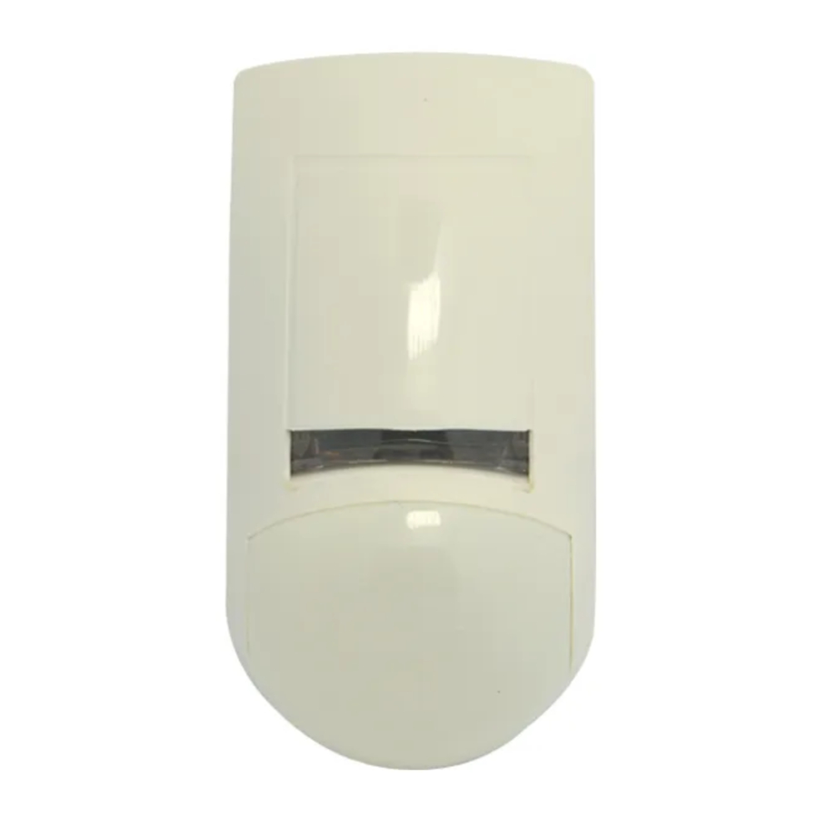
SRDT-15 FEATURES
A new generation of professional movement spread spectrum analyzing PIR & MW detectors.
- Dual element PYRO sensor and hard lens for outstanding detection performance and elimination of false alarms.
- Microwave detection based on Doppler concept.
- Unique Microwave Motion Sensor Module with microstrip patch antenna.
- VLSI based electronics with movement speed spectrum analysis.
- AND & OR alarm signal selection.
- Height installation calibrations free.
- User-friendly installation with or w/o swivel bracket.
- 2-way Microwave sensitivity adjustment.
- 2-way PIR sensitivity adjustment.
- BI directional temperature compensation.
- Environmental immunity.
The SRDT-15 is a combination of PIR & MW detectors, providing protection from intruders by PYRO sensor element and MW (based on Doppler concept).
Using micro controller for PIR & MW signal analyzing, with special ASIC technology for PIR pulse processing, assure "false alarm free" operation.
MOUNTING THE DETECTOR
Choose a location most likely to intercept an intruder. (Our recommendation is a corner installation). See detection pattern in Fig.: 5, 6. The dual-element high quality sensor detects motion crossing the beam; it is slightly less sensitive detecting motion toward the detector. The SRDT-15 performs best when provided with a constant and stable environment.
NOTE: recommended installation height is 2.1m (option: 1.5m to 3.0m).
FIG. 5 - WA PIR + MW DETECTION PATTERN

FIG. 6 - LONG RANGE CURTAIN LENS

AVOID THE FOLLOWING LOCATIONS
- Facing direct sunlight.
- Facing areas subject to rapid quick temperature changes.
- Areas with air ducts or substantial air flows.
- Facing metal doors.
WIRE SIZE REQUIREMENTS
Use the following table to determine required wire gauge and length.
| Wire Diameter | mm | .5 | .75 | 1.0 | 1.5 |
| Wire Gauge: | # | 22 | 20 | 18 | 16 |
| Wire Length: | m | 205 | 310 | 510 | 870 |
| Ft. | 800 | 1200 | 2000 | 3400 |
REMOVAL OF FRONT COVER
- To remove the front cover, insert a flat screwdriver in the slot between the front and the bottom above the holding screw hole and push gently, until the front cover is disengaged and the opening click is heard. (Fig. 1)
FIG. 1 - REMOVAL OF FRONT COVER

- Remove the printed circuit board by spread out the two tabs, which are located on the either side of the lower half of the board.
- Break out the desired holes for proper wiring.
- Insert the wire through the wire access hole, and mount the detector base to the wall, corner or ceiling with the necessary number of screws and the suitable bracket.
- Reinstall the PC board by place it on the lower stoppers and push the PCB toward the bottom cover.
- Access for wiring connections is easy via the terminal block located on the PCB. (Fig. 3)
- Replace the cover by inserting it back in the appropriate closing pin until the closing click is heard.

FIG. 3 - TERMINAL BLOCK CONNECTIONS

Terminal 1 – Marked " - " (GND)
Connect to ground of the control unit.
Terminal 2 – Marked " + " (+12V)
Connect to a positive Voltage output of 8.2 -16Vdc source (usually from the alarm control unit)
Terminals 3 & 4 - Marked "RELAY"
These are the output relays contacts of the detector. Connect to a normally closed zone in the control unit.
Terminals 5 & 6 - Marked "TAMPER"
If a Tamper function is required connect these Terminals to a 24-hour normally closed protective zone in the control unit. If the front cover of the detector is opened, an immediate alarm signal will be sent to the control unit.
KNOCKOUT HOLES
FIG. 2 - KNOCKOUT HOLES

- Wire access holes
- Use for flat wall mounting
- Corner mounting - use all 6 holes. Sharp left or right angle mounting - use 3 holes (top, middle and bottom)
- For bracket mounting
MW SENSITIVITY ADJUSTMENT
JUMPER "JP1" - provides sensitivity control of MW (DOPPLER) according to the environment.
Position Up – "H" – High sensitivity
For normal operation – immediately detection.
Position Down – "L" – Low sensitivity
For harsh environments.
POTENTIOMETER "RV1" – adjustment according to protected area range.
The potentiometer at mid-scale is equivalent to a distance of 15m, at min-scale – 7m and max-scale - is used with LR lens only.
Dimension change according to installation location and room size
PIR SENSITIVITY ADJUSTMENT
JUMPER "JP4" - provides sensitivity control of PIR according to the environment.
Position Up – "H" – High sensitivity
For stable environments.
Position Down – "L" – Low sensitivity
For harsh environments.
POTENTIOMETER "RV2" – adjustment according to protected area range.
Use RV2 to adjust the detection range between 68% and 100% (factory set to 84%). Rotate the potentiometer clockwise to increase range, counter-clockwise to decrease range.
After adjusting the sensitivity perform a walk test to verify optimum correct sensitivity in the protected area.
ALARM MODE SETTING
JUMPER "JP2" OR - AND
Position Left "OR"
The alarm signal (relays activation) occurred when one of the sensor's signals - PIR OR MW - is present.
The effective detection range is the range of the PIR pattern OR MW pattern correspondently.
Position Right "AND" - The alarm signal occurred only when both sensors (PIR AND MW) are present at the same time.
The effective detection range is the range of which the PIR patterns AND MW lobe are intersected.
You must reset the detector from Control Panel before the new settings will take effect.
LED ENABLE/DISABLE SETTING - JUMPER "JP3" (FIG.4)
FIG. 4 - PCB LAYOUT

Position On (right) - LED ENABLE
The RED LED will activate when the SRDT-15 Is in alarm condition.
Position Off (left) - LED DISABLE
The LEDS are disabled.
Note: the state of the Jumper "JP3" does not affect the operation of the relay.
When an intrusion is detected, the LED will activate and the alarm relay will switch into alarm condition for 1.6 sec.
LED INDICATORS (Fig.4)
YELLOW LED - MW detection's
GREEN LED - PIR detection's
RED LED - Alarm
TEST PROCEDURES
Wait one-minute warm-up time after applying 12 Vdc power. Conduct testing with the protected area cleared of all people.
Walk test
- Remove front cover. Set LED to ON position.
- Reassemble the front cover.
- Start walking slowly across the detection zone.
- Observe that the red LED lights whenever motion is detected.
- Allow 5 sec. between each test for the detector to stabilize.
- After the walk test is completed, you can set the LED to OFF position.
NOTE:
Walk tests should be conducted, at least once a year, to confirm proper operation and coverage of the detector.
PATTERN SCALE CALIBRATION
To calibrate the MW pattern scale, You need the size of the room (length and detection angle).
For Doppler pattern see fig.7 and table1, where
H – Doppler pattern max;
## - zone number;
a – angle;
X,Y – appropriate coordinates of Doppler pattern.
FIG. 7 - MW PATTERN

Table 1:
| ## | 0 | 1 | 2 | 3 | 4 | 5 | 6 | 7 | 8 | 9 | 10 |
| a | 180° | 130° | 100° | 84° | 75° | 70° | 60° | 52° | 40° | 30° | 20° |
| X | 0 | 3 | 6 | 9 | 12 | 15 | 18 | 21 | 24 | 27 | 28,5 |
| Y | 10,5 | 6,09 | 7,15 | 6,98 | 8,01 | 10,5 | 10,39 | 10,24 | 8,73 | 7,23 | 5,03 |
X,Y are corresponds (m) of pattern points when H=30m
The potentiometer RV1(Fig. 4) adjusts the detection pattern scale between 30% and 100% (factory set to 70%). Rotate the potentiometer clockwise to increase pattern scale.
Rotate the potentiometer counter-clockwise to decrease pattern scale.
The potentiometer at min. " – " is equivalent to a distance of 6m - 8m.
LENSES-INTERCHANGEABLE HARD TYPE SPHERICAL LENSES PATTERNS
| COVERAGE | WIDE ANGLE | LONG RANGE CURTAIN | ANIMAL ALLEY | CURTAIN |
| 18m x 18m (60ft x 60ft) ±10% | 30m x 2m (100ft x 6.3ft) ±10% | 18m x 18m (60ft x 60ft) | 15m x 1m (50ft x.3ft) | |
| TOTAL ZONES | 52* | 12 | 18 | 22 |
* 18 long range, 16 intermediate, 10 short range, 6 nearest range, 2 creep zones.
REPLACING THE LENS
FIG. 8 - REPLACING THE LENS

- Remove the front cover by inserting a flat screwdriver in the appropriate slot.
- Using a small flat screwdriver, press on left or right side of the installed lens, which will then pop out, from its side right and left holding pins.
- Select the desired lens and hold it while making sure its upper holding pin is pointed upwards.
- Snap the lens to its place by pressing again from outside of the front cover until a click is heard, confirming the new lens is tightly inserted.
- Replace front cover.
TECHNICAL SPECIFICATIONS
| Detection Method | Dual element PIR & microwave pulse Doppler |
| Power Input | 8.2 to 16 Vdc |
| Current Draw | Active: 25.5 mA Standby: 16.5 mA |
| Temperature Compensation | YES |
| Alarm Period | 2 +/- 1 sec |
| Alarm Output | N.C 28Vdc 0.1 A with 10 Ohm series protection resistors |
| Tamper Switch | N.C 28Vdc 0.1A with 10 Ohm series protection resistor - open when cover is removed |
| Warm Up Period | 1 min |
| LED Indicator | Yellow LED is blinking during warm up period and self testing, Red LED is ON during alarm Red LED: UNIT ALARM Green LED: PIR CHANNEL Yellow LED: MW CHANNEL |
| Operating Temperature | -20°C to +50°C(-4°F to +122°F) |
| RFI Protection | 30V/m 10 - 1000MHz |
| EMI Protection | 50,000V of electrical interference from lightning or power through |
| Visible Light Protection | stable against halogen light 2.4 m (8ft) or reflected light |
| MW center frequency | 2.45 GHz |
| MW output power | min + 5 dBm IERP |
| MW harmonic emission | -20 dBm |
| Dimensions | 137mm x 70mm x 53mm (5.3" x 2.8" x 2.1") |
| Weight | 130 gr. (4.,6 oz) |
CROW reserves the rights to change specifications without prior notice

Documents / ResourcesDownload manual
Here you can download full pdf version of manual, it may contain additional safety instructions, warranty information, FCC rules, etc.
Download Crow SRDT-15 - Passive Infrared & Microwave Detector Installation Manual
Advertisement


Need help?
Do you have a question about the SRDT-15 and is the answer not in the manual?
Questions and answers