Table of Contents
Advertisement
Quick Links
1
TL - 360
4 ELEMENT
CEILING MOUNT
PASSIVE INFRARED DETECTOR
TALON SERIES
INSTALLATION INSTRUCTIONS
P/N 7111069 REV.1 A.Y.
4
MOUNTING THE DETECTOR
Choose location most likely to intercept an
intruder. Refer to the detection pattern.
1. Hold the detector in your hand and
release the mounting plate by turning
it counter-clock-wise, and separate it
from the case (Fig. 1).
2. Insert the wires through the hole in the
center of the mounting plate (Fig. 2).
3. Mount the plate using the holes
marked mounting holes.
WIRE SIZE REQUIREMENTS
Use #22 AWG (0.5 mm) or wires with a
larger diameter. Use the following table to
determine required wire gauge (diameter)
and length of wire between the detector
and the control panel.
Wire Length
m 200 300
Wire Diameter mm .5
.75
Wire Length
ft. 800 1200 2000 3400
Wire Gauge
#
22
20
7
TERMINAL BLOCK CONNECTIONS
12VDC
RELAY TAMPER MEM
-
+
NC
NC
1
2
3
4
5
6
Run the cable through the cable entry hole
and connect the wires in accordance with
the following instructions:
Terminal 1 - Marked " - " ( GND )
Connect to ground of the control panel.
Terminal 2 - Marked " + " ( + 12V )
Connect to a positive Voltage output of
8.2-16 Vdc source (usually from the alarm
control unit).
Terminals 3 & 4 - Marked " RELAY "
These are the output relay contacts of the
detector. Connect to a normally closed
zone in the control panel.
Terminals 5 & 6 - Marked " TAMPER "
If a Tamper function is required connect
TL-360 FEATURES "Super Catch"
∗ Fully sealed sensor chamber.
∗ VLSI Technology (Very Large Scale
Integration).
∗ Maximum RFI & EMI Immunity.
∗ 4 Element Pyro Sensor.
∗ Pulse Count.
∗ Sophisticated signal processing.
∗ Memory function.
∗ Hard Spherical Lens 360° coverage.
∗ Bidirectional temperature
compensation.
∗ Flourescent light stability.
INTRODUCTION
The TL-360 is a 4-element passive infrared
intrusion detector for use in electronic
security systems in ceiling mount
applications.
You will obtain optimum performance from
your TL-360 PIR detector by following this
manual.
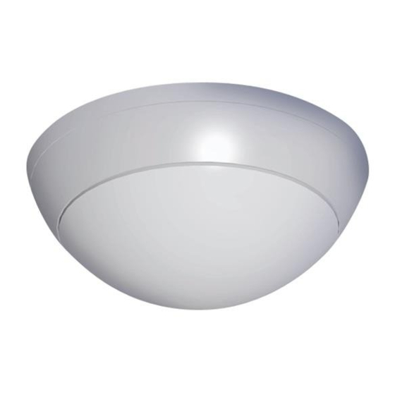
FIG. 1 - TL-360 . EXTERNAL VIEW
OPEN
Separate cover
from base
400
800
1.0
1.5
18
16
these terminals to a 24 hour normally
closed protective zone in the control unit. If
the front cover of the detector is opened,
an immediate alarm signal will be sent to
MEM
the control unit.
Terminal 7 - Marked " MEM "
7
The alarm memory function allows the
identification of an alerting detector out of
multiple detectors connected to one (or the
same) zone of the control unit.
To enable this function, connect (switch
on) the M terminal to a switched +12 to
+16V
source (e.g. Arm / Disarm voltage
DC
output from the control unit.)
In case of an alarm, the memory function
stores the alarm event in the detector.
To identify the detector that alarmed,
disconnect (switch off) (grounded) the
voltage from MEM terminal.
The LED of the detector with the alarm
event in memory will light constantly until
memory function is reset.
To reset the memory function, switch on
and switch off the M terminal.
2
5
CLOS
O
C
8
3
The TL-360 reduces false alarms to an
unprecedented minimal level due to its
effective elimination of background noises
and nuisance stimuli. The TL-360 employs
Automatic Pulse Count making it extremely
adaptable to various environments. The
unique VLSI, using sophisticated signal
processing, makes this detector virtually
free of false alarms.
The TL-360 integrates VLSI & SMD (surface
mount device) to their full advantage.
The detector is easy to install, with no
necessary adjustments.
HARD SPHERICAL LENS
The TL-360 is equipped with a special hard
lens. This lens is the latest development in
the security field and complies with all the
new standards requirements. It gives wide
coverage patterns, even at low mounting
heights. It is especially immune to sunlight,
halogen lights and fluorescent lights and is
impervious to attack.
6
FIG. 2 - TL-360. INTERNAL VIEW
Terminal Strip
Pulse Count
Switch
Rubber
Insulation
Sensitivity/Range
Adjustment
9
PULSE COUNT SETTING - Slide switch
(Fig.3). Provides control for normal or high
risk operating environments.
Position 1 (to left)
For stable environments.
Position AUTO (to right)
For harsh environments.
This setting enables special software to
modify detection speed.
When an intrusion is detected, the LED will
activate and the alarm relay will switch into
alarm condition (open circuit) for 1.6 sec.
To change position of the slide switch you
have to open the detector:
1. Turn the detector counter-clock wise
and separate it from the mounting base.
2. Change position of the slide switch.
3. Close the detector and reinstall
assembly screws.
Advertisement
Table of Contents

Subscribe to Our Youtube Channel
Related Manuals for Crow TL-360


Summary of Contents for Crow TL-360
- Page 1 ∗ Flourescent light stability. necessary adjustments. HARD SPHERICAL LENS INTRODUCTION The TL-360 is equipped with a special hard The TL-360 is a 4-element passive infrared lens. This lens is the latest development in intrusion detector for use in electronic the security field and complies with all the security systems in ceiling mount new standards requirements.
- Page 2 ≥ 30V/m RFI Protection Fort Lee, N.J. 07024, USA description on the face hereof. In no case shall CROW be liable to 10 - 1000MHz Tel: 1-800-GET CROW anyone for any consequential or incidental damages for breach of this or...
Need help?
Do you have a question about the TL-360 and is the answer not in the manual?
Questions and answers